Do you have a question about the Roche cobas Urisys 1100 and is the answer not in the manual?
Details implementing physical controls and unique operator IDs for system access and data security.
Highlights the importance of password protection to prevent data compromise and unauthorized access.
Explains the electro-optical reading process using LEDs and a phototransistor to measure reflectance.
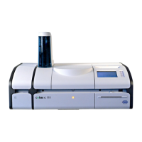
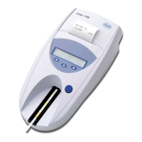
Details the physical components of the Urisys 1100 analyzer and their respective functions.
Includes warnings about reading the manual, acclimatizing the unit, checking contents, and avoiding interference.
Steps to unpack, place, and connect the analyzer to power.
Instructions on how to recalibrate the analyzer using Control-Test®M strips.
Step-by-step guide for placing the strip, pressing START, and reading the results.
Explains how valid calibration results are printed and the system's weekly calibration reminders.
Details error messages like E1, E5, E16 and procedures to resolve them.
Ensures analyzer function by measuring QC material and comparing results against known ranges.
General instructions on inserting a strip and pressing START to commence reading.
Step-by-step guide for performing a measurement in Normal Mode.
Instructions for dipping the strip, removing excess urine, and placing it in the tray.
Describes the sequence of events during measurement and the output of results.
Steps for performing serial readings with external incubation.
Covers entering patient ID, operator ID, and authentication details.
Details data transmission methods to PCs or host computers.
Instructions for cleaning the analyzer's exterior parts using a damp cloth with detergent or disinfectant.
Procedures for wiping residues after each reading and daily cleaning of the tray.
Steps for cleaning the tray: switching off, rinsing, disinfecting, and drying.
Details errors related to the reference pad (middle, bottom, top) and troubleshooting steps.
Covers 'STRIP MEAS. ERROR!' cause and actions like repeating the measurement.
Details 'CALIBRATION ERROR!' and 'CALIBRATION INVALID!' causes and troubleshooting.
Troubleshooting for 'CHIP ERROR!' (program chip) and 'MISSING TRAY!' errors.
Explains 'TRAY POSITION ERROR!' causes like soiling or mechanism fouling.
Troubleshooting for incorrect tray usage and light barrier issues.
Details causes and actions for 'MOTOR STEP ERROR!' related to tray movement.
Troubleshooting for optics errors and printer cover/paper issues.
Covers faults in data transfer and actions to resolve 'INTERFACE ERROR!'
Details connecting to PCs/hosts via the serial interface and communication modes.
Explains using barcode readers or keyboards for data entry.
General safety requirements and warnings for proper analyzer operation.
| Type | Urine Analyzer |
|---|---|
| Sample Type | Urine |
| Measurement Principle | Reflectance photometry |
| Display | LCD |
| Parameters | pH, Protein, Glucose, Ketones, Hemoglobin, Nitrite, Urobilinogen, Bilirubin, Specific Gravity, Leukocytes |
| Interfaces | RS-232, USB |
| Power Requirements | 100-240 V AC |
| Operating Temperature | 15 – 32 °C (59 – 90 °F) |
| Operating Humidity | 20 – 80% relative humidity, non-condensing |
| Test Parameters | Leukocytes, Nitrite, Urobilinogen, Protein, pH, Blood, Glucose, Ketones, Bilirubin |
| Data Storage | Up to 1000 patient results |