100 Rockwell Automation Publication 2080-QS004C-EN-E - October 2023
Appendix A Set Up Serial Communication Between Computer and Micro820 Controller
To connect the computer to the Micro820 controller using the serial port on the computer, or the USB-Serial adapter, you must modify a
cable so that it has a 9-pin D sub connector on one end and exposed wires on the other end. Here, we use the Allen-Bradley® communication
cable (1761-CBL-PM02).
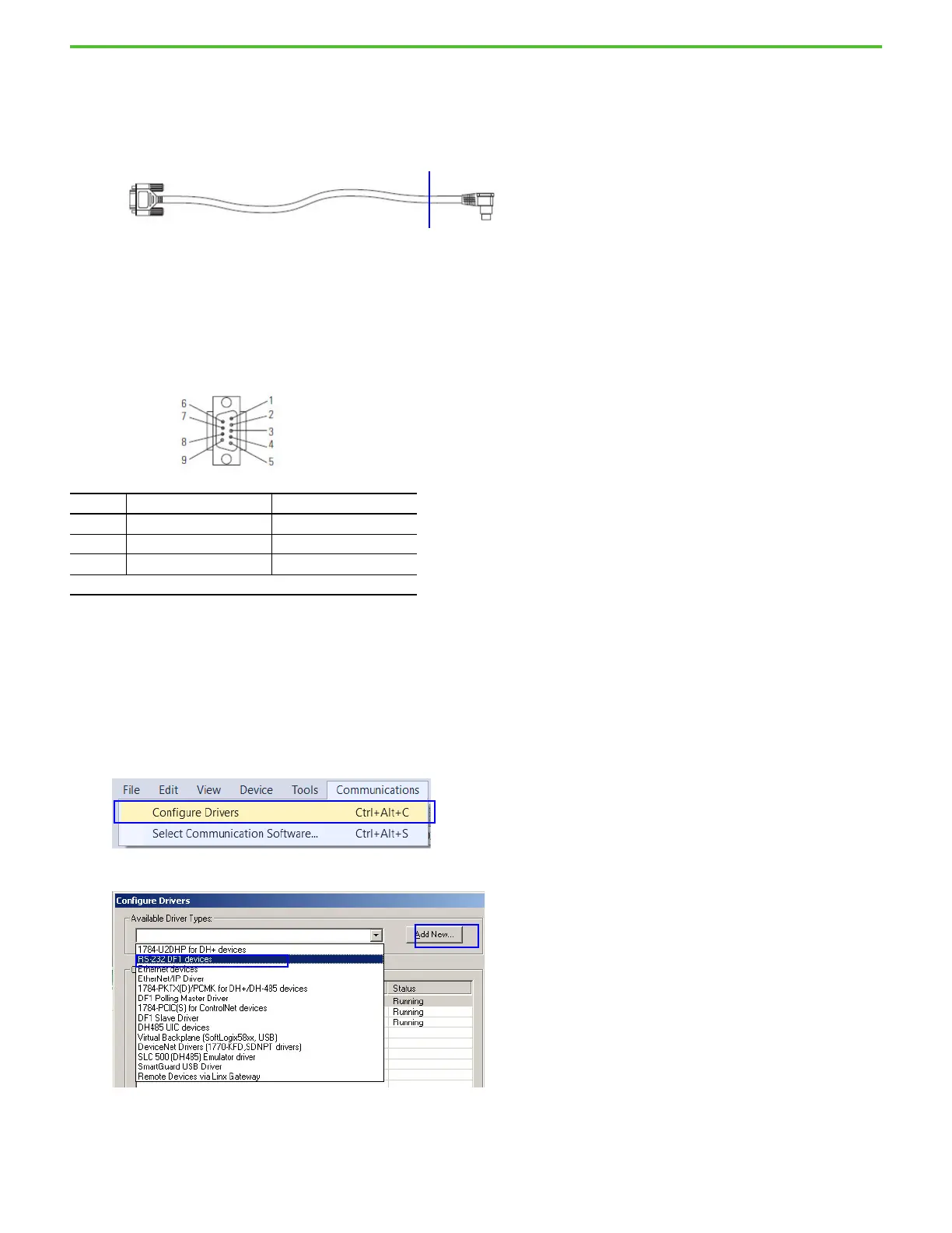
Modifying the 1761-CBL-PM02 Cable
The 1761-CBL-PM02 cable has an 8-pin mini DIN connector on one end and a 9-pin D sub connector on the other end. Cut the cable at any
point near the end with the 8-pin mini DIN connector to expose the wires.
Alternatively, you can customize your own cable with a DB9 receptacle on one end. The cable length must not exceed three meters (10 feet).
1761-CBL-PM02 Pinout Diagram
1. Connect the exposed wires of the cable to the Micro820 controller.
2. Connect the other end of the cable to your computer serial port or a USB-Serial adapter.
Configure RSLinx
When using the 2080-REMLCD, the DF1 driver is automatically added when the USB cable is connected to the computer and no RSLinx
configuration is needed. When using the embedded serial port on the computer, or USB-Serial adapter, you must manually add the DF1 driver.
1. In Connected Components Workbench software, select Communications > Configure Drivers.
2. Select RS-232 DF1 devices from the dropdown menu and select Add New.
Pin DB-9 RS-232 Micro820
2 Received data (RxD) Tx terminal
3 Transmitted data (TxD) Rx terminal
5 Signal common (GRD) G terminal
The rest of the pins and terminal connections are not required.
 Loading...


