Rockwell Automation Publication 2080-QS004C-EN-E - October 2023 31
Chapter 6
Monitor Your Micro800 Controller Program
Monitor Your Program in Connected Components Workbench Software
When connected to your Micro800 controller in Connected Components Workbench software:
• You can view your program visually in real-time and watch values change in the program.
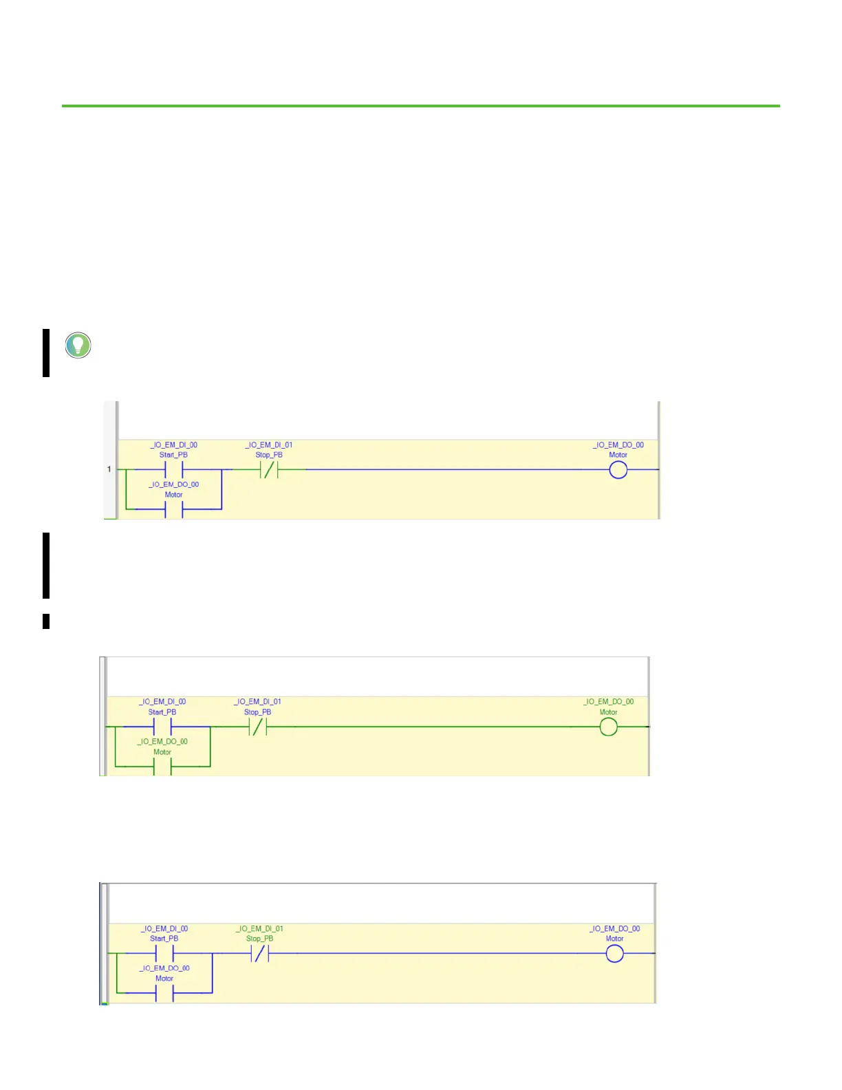
• You should see the Ladder Diagram change color as the inputs and outputs change state.
Individual Boolean instructions are green if the instruction result is TRUE/ON or blue if the result is FALSE/OFF. The rung starts from
the left power rail with the color green, which indicates TRUE/ON, and flows to the right. Any FALSE/OFF instruction, which is blue,
interrupts the flow. There must be at least one complete green path to the output for the output to be TRUE/ON.
1. Toggle the simulator board switch SW11 ON and OFF. Observe the _IO_EM_DI_00 Direct Contact instruction turn green as you toggle on
the switch, and then turn blue as you release it (if you toggle and release the switch too fast, you may not see it update in the Ladder
Diagram). Then observe the _IO_EM_DO_00 Direct Contact and Direct Coil instructions turn green. You should also observe that the
output indicator light 0 on the controller is now lit.
This is a typical motor seal-in circuit (and can also be applied in non-motor circuits). The Output Coil is turned on with a Direct Contact
and then the active state of the Output Coil seals in the circuit. The circuit is unsealed when a Reverse Contact (normally closed) is
opened.
2. Toggle the simulator board switch SW12 ON to turn off the output. Observe the output _IO_EM_DO_00 on your controller turn off and
the corresponding changes in your Ladder Diagram.
In Connected Components Workbench software:
• The color for the TRUE/ON state is green for version 22 or later.
• The color for the TRUE/ON state is red for version 21.01 or earlier.
 Loading...


