Rockwell Automation Publication 2080-QS004C-EN-E - October 2023 47
Chapter 9 How to Add a Plug-in Module
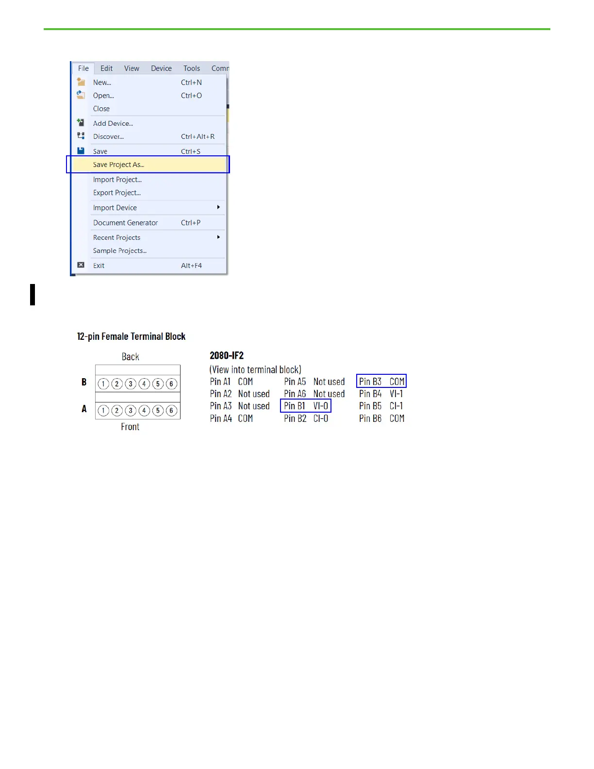
9. Save your project and download it to the controller. You can save your project by selecting File > Save.
10. Connect the analog voltage output from the simulator board to Channel 0 of the 2080-IF2 module. For this example, we use the analog
output voltage as the input for Channel 0.
11. Connect the analog output to Pin B1 (VI-0) and the analog output ground to Pin B3 (COM).
12. Double-click Global Variables in the Project Organizer.
13. Locate the variable _IO_P1_AI_00. This is the raw data value in relation to the voltage that is wired to Channel 0. The value ranges
from 0...65535 in relation to a 0...10 volt input.
 Loading...


