30 Rockwell Automation Publication 2198-RM003B-EN-P - November 2020
Chapter 2 Replacement Considerations
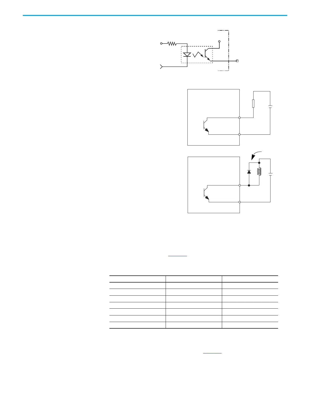
Figure 3 - Ultra3000 Digital Output Circuit
Figure 4 - Kinetix 5100 Drive Digital Output Circuits
Analog Inputs
This section describes analog inputs for Ultra3000 (Non-Sercos) and
Kinetix 5100 servo drives. Table 26
compares the analog inputs of these two
drives.
The Ultra3000 drive analog COMMAND input can receive a position, velocity,
or current command signal. A 14-bit A/D converter digitizes the signal. The
characteristics of this input are shown in Figure 5
.
Table 26 - Analog Inputs Parameters Comparison
Parameter Ultra3000 Drives Kinetix 5100 Drives
Analog Inputs Resolution 14 bits 15 bits min
Analog Inputs Impedance 20 kΩ Approx. 12 kΩ typical
Analog Inputs Voltage -10…+10V -10…+10V
Analog Inputs Scan Time 0.0625 ms 0.0625 ms max
Offset Error 50 mV 50 mV max
Gain Error 1% 1% max
Propagation Delay 100 µS 100 μS max
200 Ω
+5V
OUTPUT
IOPWR
OUT
TLP127
OUTPUTx–
OUTPUTx+
24V DC
R
OUTPUTx–
OUTPUTx+
24V DC
The servo drive applies external power supply
and the load is resistive.
The servo drive applies external power supply
and the load is inductive.
Kinetix 5100 Servo Drive.
Kinetix 5100 Servo Drive.
Confirm the polarity of the
diode is correct or it may
damage the servo drive.

 Loading...


