Rockwell Automation Publication 7000-UM202H-EN-P - November 2023 163
Chapter 3 Control Component Definition and Maintenance
Positional Encoder Operations
Besides quadrature encoders, the universal encoder interface also accepts
positional (absolute) encoders. The interface converts parallel positional data
to a serial stream and transmits it to the DPM. The board also generates
“pseudo” quadrature differential signals, including a zero position mark,
derived from the binary data to the DPM.
There are three different positional encoder configurations available. For all of
these configurations remove the ENC_TYPE jumper. The other jumpers
configure the board for the type of positional data (gray code or natural binary)
set by CD_DQUAD and high or low true data set by POL_QRDNT.
• Gray code, low true. In this configuration the board inverts the incoming
gray code data then converts it to binary for transmission to the DPM.
• Natural binary, low true. The board does not convert incoming data but
does invert it.
• Gray code, high true. The board converts incoming gray code data to
binary without inverting the input data.
• Natural binary, high true. The board converts positional data to the serial
stream without inverting or converting it.
Positional Encoder Guidelines
When selecting a positional encoder, follow these guidelines for optimal
performance.
1. Code Selection: Purchase absolute encoders with either Gray code or
Binary output format. Gray code is a form of binary code, where only a
single bit changes at a time for each sequential number or position. The
fact that only a single bit changes at a time makes it easier for the
Universal Encoder Interface to read valid positional data and not
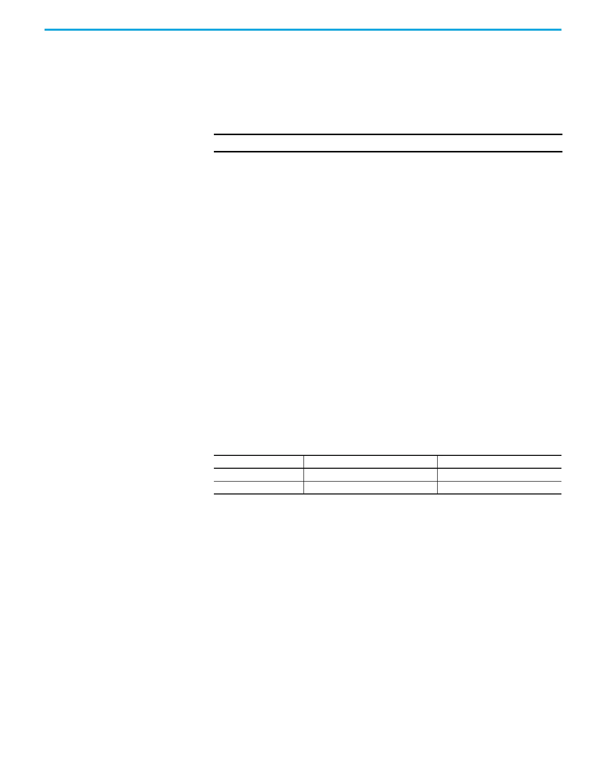
ambiguous data. If we compare the Natural Binary code to Gray code for
the transition from 255 to 256, we see:
All nine bits changed in the Binary Code, while only the MSB of the Gray
code changed. In the Universal Encoder Interface, the frequency filter
components and input hysteresis create delays. Differences in these
delays could cause errors due to reading a bit as ON when switching to
OFF or vice versa. In the case of Gray code, since only one bit ever
changes, the ambiguity error is never more than one count. For this
reason, and to reduce inrush currents, Rockwell Automation
recommends using Gray code Positional Encoders.
2. Data Polarity: Absolute encoders typically have a High True output. If the
encoder model does not have a High/True (or Non Inverted/Inverted)
option, you should assume it to be High True. In the case of a 10bit High
True encoder, the zero position is represented by 0000000000. In a Low/
True encoder, the zero position is 1111111111. On the Universal Encoder
Interface, the position data is inverted in hardware. That is, a ‘1’ will turn
on an optocoupler producing a ‘0’. Therefore, a High True encoder would
produce 1111111111 for the zero position. With the POL_QRDNT jumper,
you can control the polarity of the input. With the jumper installed
(factory default), it is set to accept High True encoders, and an extra
inversion is done in the Universal Encoder Interface. If you are using a
Low True encoder, then this jumper needs to be removed so that the zero
position is inverted by the optocouplers alone.
IMPORTANT Consult the factory for availability of positional encoder options.
Binary Code Gray Code
255 011111111 010000000
256 100000000 110000000

 Loading...


