Rockwell Automation Publication 7000-UM202H-EN-P - November 2023 87
Chapter 2 Power Component Definition and Maintenance
Uniform Clamping Pressure Always maintain proper pressure on the thyristors. Follow this procedure
whenever changing devices or loosening the clamp completely.
1. Apply a thin layer of electrical joint compound (Alcoa EJC No. 2 or
approved equivalent) to the clamp head pressure pad face (Figure 80
).
Apply the compound using a small brush, and gently wipe the pad face
with an industrial wipe until a thin film remains. Ensure no brush
bristles remain.
2. Torque the heatsink bolts to 13.5 N•m (10 lb•ft.), then loosen each bolt two
complete turns.
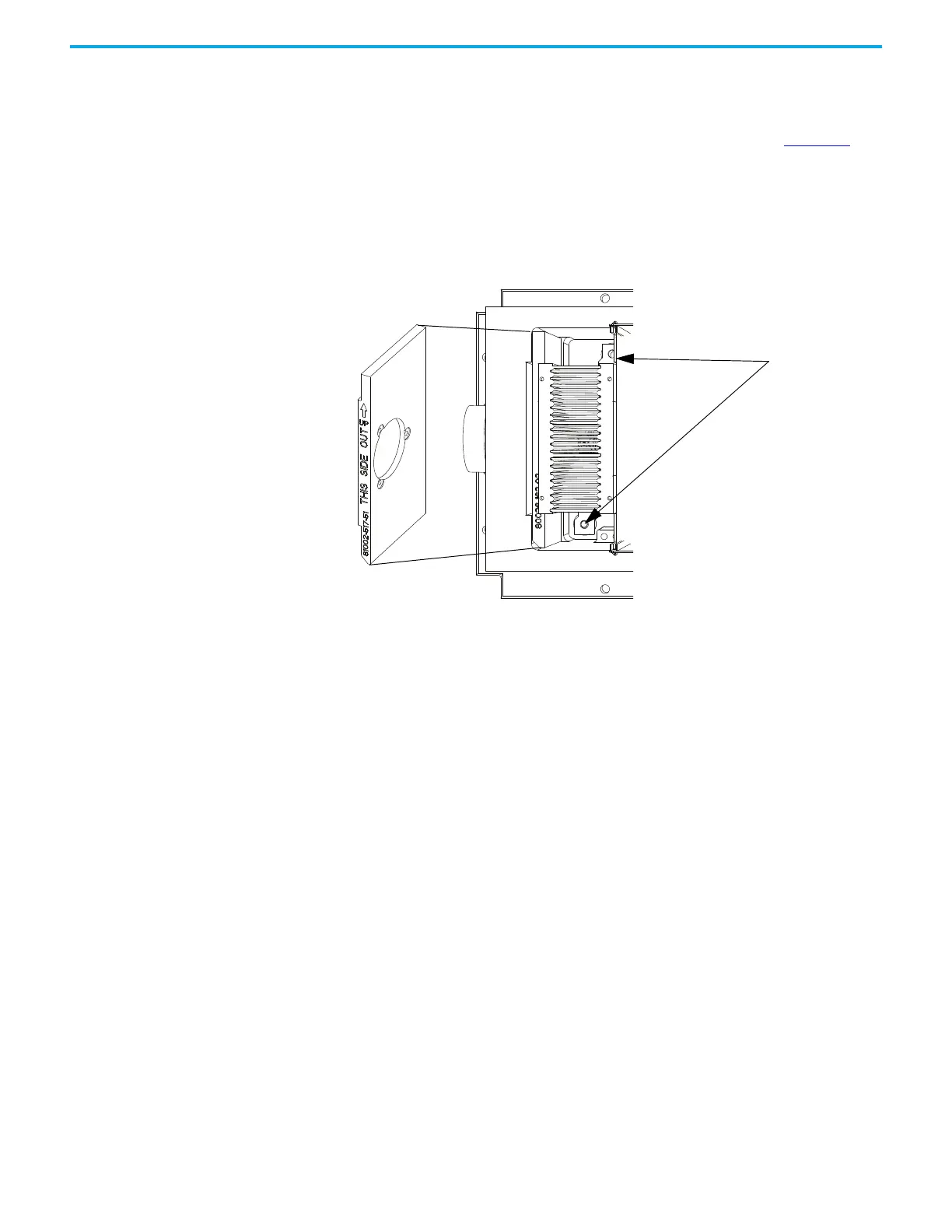
Figure 79 - Location of Heatsink Bolts
3. Tighten the clamp to the proper force until you can turn the indicating
washers by the fingers with some resistance.
4. Torque the heatsink bolts to 13.5 N•m (10 lb•ft) starting with the center
heatsink and moving outward alternating left to right.
5. Check the clamp indicating washer.
Heatsink bolt location
Do NOT remove the pivot plate from
the PowerCage when changing
devices. If the pivot plate is
removed from the PowerCage,
install it in the proper orientation
per the stamping on the side.
 Loading...


