EasyManuals Logo

Rockwell Automation PowerFlex 7000 User Manual

Rockwell Automation PowerFlex 7000
214 pages
To Next Page IconTo Next Page
To Previous Page IconTo Previous Page
Page #148 background imageLoading...
Page #148 background image
148 Rockwell Automation Publication 7000-UM202H-EN-P - November 2023
Chapter 3 Control Component Definition and Maintenance
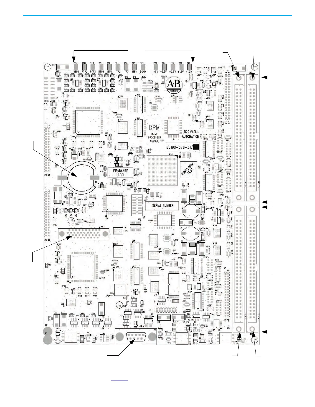
Drive Processor Module This board contains control processors, which are responsible for all the drive
control processing and stores the parameters used for the drive control.
Figure 128 - Drive Processor Module (DPM)
Diagnostic test points on the DPM have a voltage output range of -5…+5V.
Table 8 identifies test points on the DPM.
Inverter
Gating
Signals
Rectifier
Gating
Signals
Secondary
Primary
Secondary
Primary
Test Points
Battery
HMI
Interface
Module
DPM DataPort

Table of Contents

Other manuals for Rockwell Automation PowerFlex 7000

Questions and Answers:

Question and Answer IconNeed help?

Do you have a question about the Rockwell Automation PowerFlex 7000 and is the answer not in the manual?

Rockwell Automation PowerFlex 7000 Specifications

General IconGeneral
BrandRockwell Automation
ModelPowerFlex 7000
CategoryDC Drives
LanguageEnglish

Related product manuals