164 Rockwell Automation Publication 7000-UM202H-EN-P - November 2023
Chapter 3 Control Component Definition and Maintenance
The other role of the POL_QRDNT jumper is to correct the data in the
event the encoder was mounted so that a CCW rotation produced
decreasing counts. If this is the case, the POL_QRDNT jumper should be
configured to the opposite of what it should normally be for the data
polarity. For example, if the Universal Encoder Interface is configured to
operate with High True encoders (POL_QRDNT installed), remove it to
correct for encoder mounting.
External Input/Output
Boards
The external input/output (XIO) boards connect through a network cable
(CAN Link) to the analog control board (ACB). You can connect this cable to
either XIO Link A (J4) or XIO Link B (J5). The XIO board handles all external
digital input and output signals and sends them to the ACB through the cable.
There are 16 isolated inputs and 16 isolated outputs on the card, used for
Runtime I/O including Start, Stop, Run, Fault, Warning, Jog, and External
Reset signals. The boards also handle the standard drive fault signals
(transformer/line reactor overtemperature, DC link overtemperature, etc.) and
several spare configurable fault inputs. There is a software option to assign
each XIO a specific function (general IO, external IO, or liquid cooling).
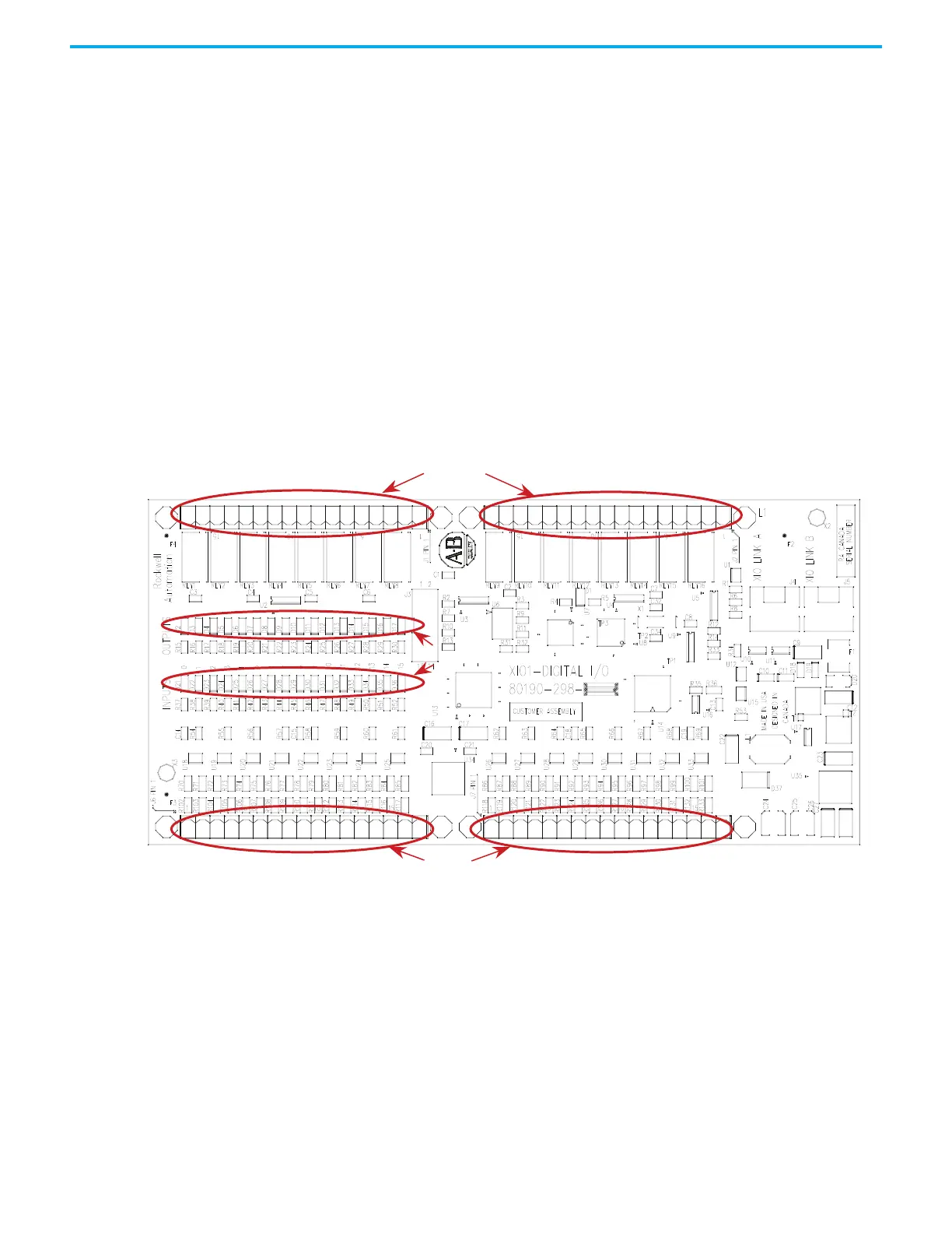
Figure 139 - XIO Board
The standard drive comes with one XIO board; additional boards (up to five)
can be daisy chained together from XIO Link B (J5) on the first board to XIO
Link A (J4) on the second board, for a total of six XIO cards. However, at this
time the drive only supports the use of addresses 1 to 3, depending on the
features and application of the drive. U6 on the XIO board displays the address
of the board which is automatically calculated from its position in the network.
XIO link A and B ports are interchangeable but it may make wiring easier to
follow if you use Link A for “upstream” (closest to the ACB), and Link B for
“downstream” (farthest from the ACB).
16 15 14 13 12 11 10 9 8 7 6 5 4 3 2 1
1 2 3 4 5 6 7 8
9 10 11 12 13 14 15 16
OUTPUTS
INPUTS
LEDS
 Loading...


