34 Rockwell Automation Publication 7000-UM202H-EN-P - November 2023
Chapter 2 Power Component Definition and Maintenance
Voltage-sensing Assembly The voltage-sensing assembly consists of the voltage sensing board and the
mounting plate. The voltage sensing board has six independent channels that
convert voltages as high as 10,800V (7.2 kV x 1.5 pu) down to low voltage levels
that the PowerFlex 7000 analog control board (ACB) can use. To measure up to
twelve independent voltage channels, link two assemblies together, with one
assembly acting as the master assembly and the second as the slave assembly.
In linked assemblies, the master assembly sends the twelve voltage signals to
the ACB. For drives requiring the synchronous transfer option, use one
additional module.
This assembly uses a separate connector to output the transfer voltages
directly to the ACB.
Table 2
shows the input voltage ranges for each input terminal on the voltage-
sensing board. There are four separate inputs taps for each independent
channel. This assembly operates at a nominal input voltage of up to 7200V with
a continuous 40% overvoltage. The output voltages scale to provide almost 10V
peak for a 140% input voltage at the high end of each of the voltage ranges.
Each channel has four taps that provide a range of input voltages and software
to provide a given amount of gain, so that 140% will correspond to the
maximum numerical value of the analogue to digital converter.
Replacing the Voltage-Sensing Circuit Board Assembly
The number of sensing boards is dependent upon the drive rectifier
configuration. To access the sensing boards in an arc resistant drive, remove
the barriers behind the swing out LV compartment.
1. Verify there is no power to the equipment.
2. Mark the position of the ribbon cables and wires.
3. Remove the screws and lift the ring lugs from the terminals to remove
the wires.
4. Release the locking mechanism located on each side of the ribbon cable
connector and pull the ribbon cable straight out to prevent bending the
pins.
5. Remove the four nuts and washers that secure the assembly to the studs
welded to the frame.
6. Remove the old VSB and replace with the new VSB on the studs, using
the existing hardware to secure the assembly. Do not over-torque the
connections or you may break the studs.
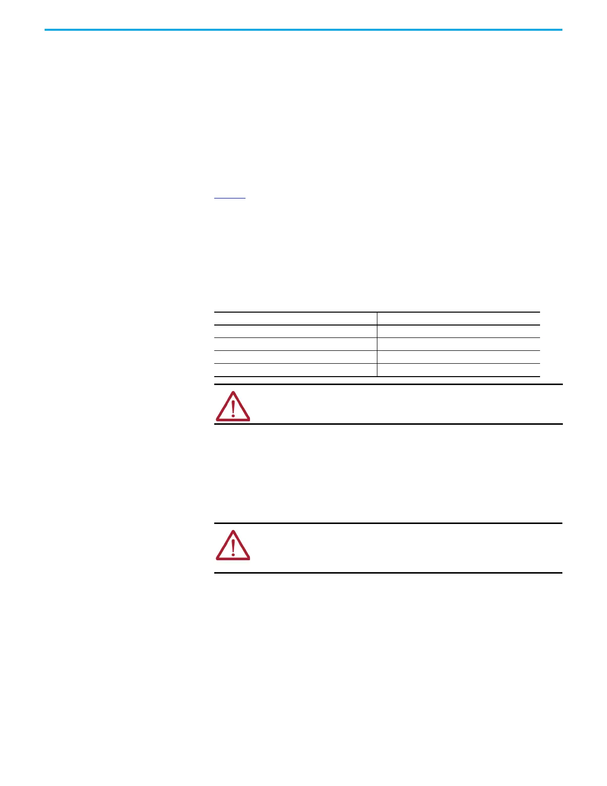
Table 2 - Nominal Input Voltage Range
Tap Voltage Range
D 800…1449V
C1450…2499V
B2500…4799V
A4800…7200V
ATTENTION: Reconnect the grounds on the voltage sensing boards. Failure
to do so may result in injury, death or damage to equipment.
ATTENTION: To prevent electrical shock, disconnect the main power before
working on the sensing board. Verify that all circuits are voltage-free, using
a hot stick or appropriate high voltage-measuring device. Failure to do so
may result in injury or death.

 Loading...


