EasyManuals Logo
Home>Rockwell Automation>DC Drives>PowerFlex 7000

Rockwell Automation PowerFlex 7000 User Manual

Rockwell Automation PowerFlex 7000
214 pages
To Next Page IconTo Next Page
To Previous Page IconTo Previous Page
Page #72 background imageLoading...
Page #72 background image
72 Rockwell Automation Publication 7000-UM202H-EN-P - November 2023
Chapter 2 Power Component Definition and Maintenance
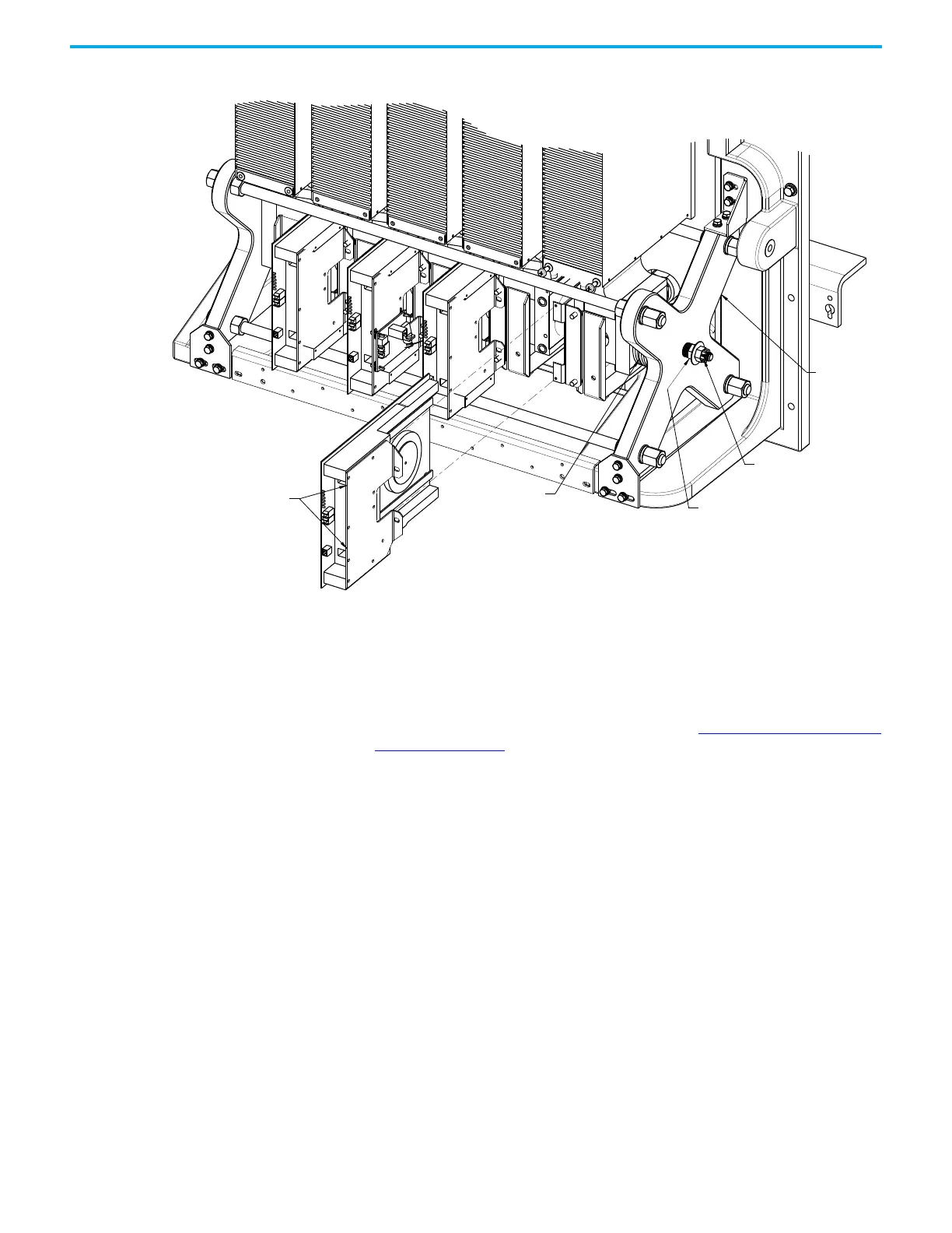
Figure 63 - Replacing the SGCT (Heatpipe Model)
Replacing Snubber and Sharing Resistor
The snubber and sharing resistors are part of the resistor assembly located
behind the PowerCage module.
1. Remove the PowerCage module as outlined in Removing the PowerCage
Module on page 97.
Note the connection of the leads for correct replacement.
2. Detach the leads located on the bottom of the resistor assembly.
Clamp Head
DO NOT ADJUST
outside nut
Inside nut used for loosening
and applying load to assembly
Disc Springs
SGCT
Captive
Screws

Table of Contents

Other manuals for Rockwell Automation PowerFlex 7000

Questions and Answers:

Question and Answer IconNeed help?

Do you have a question about the Rockwell Automation PowerFlex 7000 and is the answer not in the manual?

Rockwell Automation PowerFlex 7000 Specifications

General IconGeneral
BrandRockwell Automation
ModelPowerFlex 7000
CategoryDC Drives
LanguageEnglish

Related product manuals