82 Rockwell Automation Publication 7000-UM202H-EN-P - November 2023
Chapter 2 Power Component Definition and Maintenance
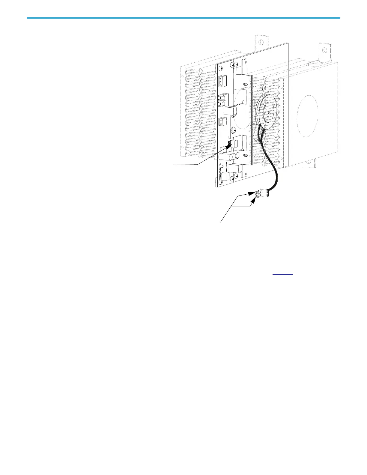
Figure 75 - SCR Gate-to-Cathode Test
The resistance value from gate-to-cathode should be between 10…20 Ω. A value
close to 0 Ω indicates that there is an internal short in the SCR. An extremely
high value indicates that the gate connection in the device has broken.
If a Gate-to-Cathode test reveals a damaged SCR, see page 85
for the SCR
replacement procedure.
Snubber Resistance (SCR Device)
Access to the snubber resistor is not required to test the resistance. The
snubber circuit test point is located within the PowerCage module under the
heatsinks. For each device, there is one test point. To verify the resistance,
measure the resistance between the test point and the heatsink above.
Test points for Gate-to-Cathode
Disconnect SCR
Phoenix
connector from
board

 Loading...


