Rockwell Automation Publication 7000-UM202H-EN-P - November 2023 77
Chapter 2 Power Component Definition and Maintenance
Silicon Controlled Rectifier
PowerCage Modules
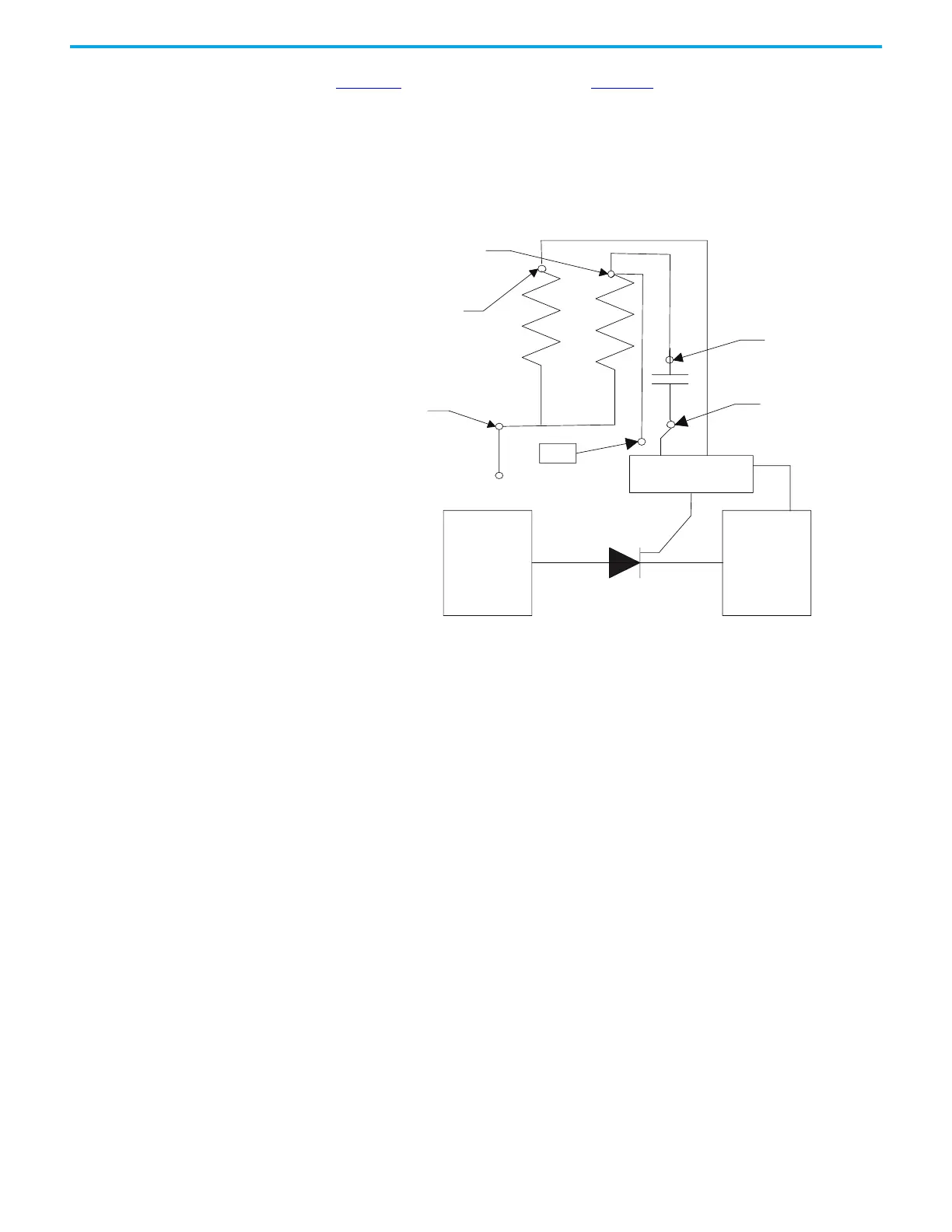
Figure 70 shows the snubber circuit. Figure 71 shows the physical locations of
the same circuit.
Disconnect the 2-pole plug to the gate driver board marked TB1 on the circuit
board. Measure the resistance from the point of the plug that connects to the
point labeled V.SENSE on the gate driver board to the anode side heatsink. A
value of 80 kΩ indicates a good sharing resistor.
Figure 70 - Snubber Circuit for SCR Rectifier Module
Rsn-2
Rsh
Rsn-1
TP
Anode
Cathode
SPGDB
Cs-1
Cs-2

 Loading...


