106 Rockwell Automation Publication 7000-UM202H-EN-P - November 2023
Chapter 2 Power Component Definition and Maintenance
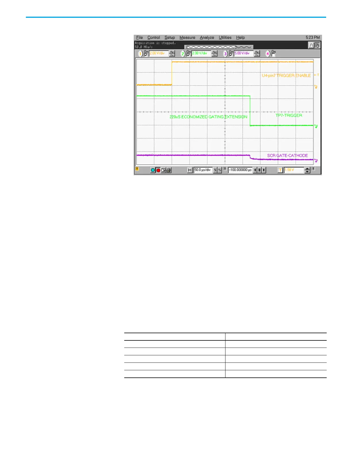
Figure 96 - Expansion of V Sense Trigger to SCR Gating Pulse
Fiber Optic Cabling The equipment uses fiber optic cabling between the low voltage control and
the medium voltage circuits. You should never need to change the routing of
the fiber optic cables.
Each end of a fiber optic cable has a connector that plugs and latches into its
respective location on a circuit board. To disconnect a fiber optic cable, depress
the ridged plastic tab at the end connector and pull. To install a fiber optic
cable insert the fiber optic port of the circuit board so that the plastic tab
latches into place.
If you must replace fiber optic cables, be careful to prevent the cables from
straining or crimping as a resulting loss in light transmission will impact
performance.
The minimum bend radius permitted for the fiber optic cables is 50 mm
(2.0 in.).
When installing the fiber optic cable, match the connector color at the end of
the cable with the connector socket color on the circuit board.
The product uses the following fiber optic cable lengths.
There is one duplex fiber optic for each thyristor, which manages gating and
diagnostic functions. The circuitry on the respective driver boards determines
the functional status of the thyristor, and sends this information to the main
processor via a fail-safe light signal in the fiber optic. The main processor
initiates the firing command for the thyristor and transmits the signal to the
appropriate gate driver board via the gating fiber optic.
Duplex Simplex
5.0 m 5.0 m
5.5 m 6.0 m
6.0 m 10.0 m
6.5 m
7.0 m
 Loading...


