Rockwell Automation Publication 7000-UM202H-EN-P - November 2023 73
Chapter 2 Power Component Definition and Maintenance
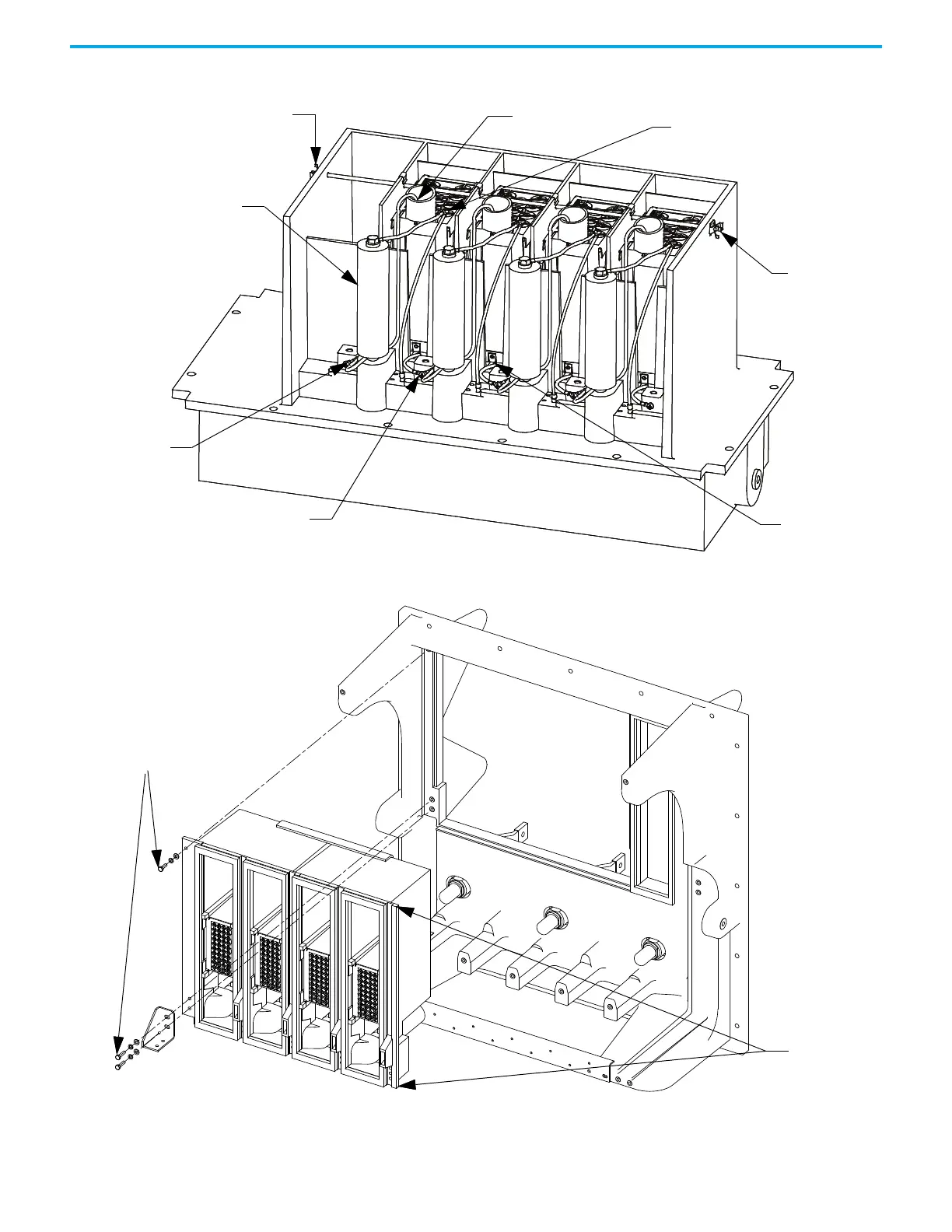
Figure 64 - PowerCage Module Removal (Heatsink PowerCage)
Figure 65 - PowerCage Module Removal (Heatpipe Model)
3. Remove the push nuts on the end of the retaining rod.
4. Pinch the clip together and pull off.
Push Nuts
Common Snubber and
Sharing Resistor
Connection
Snubber Resistor
Connection
Sharing Resistor
Connection
Push Nuts
Snubber Capacitor
Cathode
Connection
Anode Connection
Make vertical cut on
gasket at these two
locations between
resistor cage and
main PowerCage
module
Remove
Hardware

 Loading...


