74 Rockwell Automation Publication 7000-UM202H-EN-P - November 2023
Chapter 2 Power Component Definition and Maintenance
5. Pull out the retaining rod.
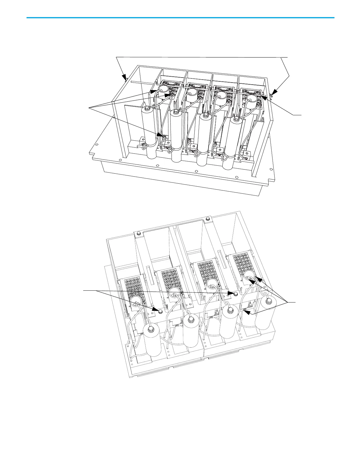
Figure 66 - Snubber and Sharing Resistor Replacement (Heatsink Model)
Figure 67 - Snubber and Sharing Resistor Replacement (Heatpipe Model)
6. Use silicone gel to secure the snubber resistor assembly to the PowerCage
module. The gel minimizes possible damages to the resistor bank during
transportation from the factory. You do not need to reapply any gel when
inserting the new resistor bank. Remove the resistor bank from the
PowerCage module.
1. Detach leads of
resistor assembly
2. Pinch and remove
clips at end of retaining
rod
3. Extract
retaining rod
Detach the leads
of the resistor
assembly
Remove hardware
for resistor
retaining bracket

 Loading...


