EasyManuals Logo
Home>Rockwell Automation>DC Drives>PowerFlex 7000

Rockwell Automation PowerFlex 7000 User Manual

Rockwell Automation PowerFlex 7000
214 pages
To Next Page IconTo Next Page
To Previous Page IconTo Previous Page
Page #75 background imageLoading...
Page #75 background image
Rockwell Automation Publication 7000-UM202H-EN-P - November 2023 75
Chapter 2 Power Component Definition and Maintenance
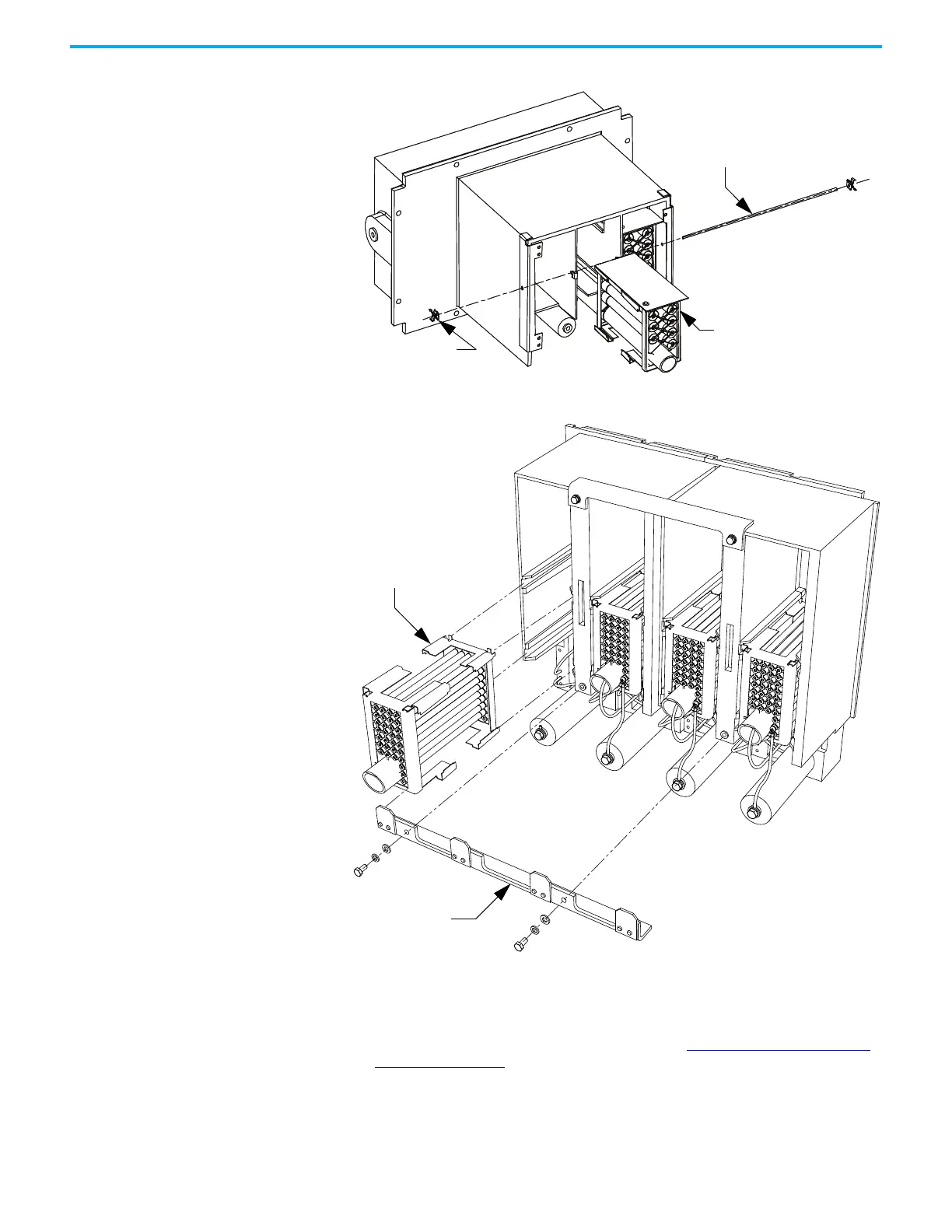
Figure 68 - Removing Resistor Bank from PowerCage Module
Figure 69 - Removing Resistor Bank from PowerCage Module (Heatpipe Model)
7. Place the new resistor bank assembly back into the PowerCage module.
8. Slide the retaining rod into place and push the clips back into place.
9. Connect the leads to the resistor bank
10. Install the PowerCage module as outlined in Removing the PowerCage
Module on page 97.
Push Nut
Resistor
Bank
Retaining Rod
Resistor Bank
Resistor Retaining
Bracket

Table of Contents

Other manuals for Rockwell Automation PowerFlex 7000

Questions and Answers:

Question and Answer IconNeed help?

Do you have a question about the Rockwell Automation PowerFlex 7000 and is the answer not in the manual?

Rockwell Automation PowerFlex 7000 Specifications

General IconGeneral
BrandRockwell Automation
ModelPowerFlex 7000
CategoryDC Drives
LanguageEnglish

Related product manuals