86 Rockwell Automation Publication 7000-UM202H-EN-P - November 2023
Chapter 2 Power Component Definition and Maintenance
12. While grounded, use a long Phillips screwdriver to remove the two
screws that hold the SCR SPGDB to the metal bracket on the red glastic
assembly. Retain the hardware.
13. Pull the four plastic clips that secure the SCR SPGDB to the glastic
assembly. Retain the hardware.
14. Install the new SCR SPGDB in the assembly with the 4 plastic clips and
use the screws to secure the board to the metal bracket.
15. Clean the heatsink with a soft cloth and rubbing alcohol.
16. Slide the SCR and SPGDB back into place until the mounting bracket
makes contact with the heatsink. Use the Phillips screwdriver to tighten
the assembly to the heatsink.
17. Reapply the clamping load as described in Uniform Clamping Pressure
on page 87.
18. Connect the control power cable and the fiber optic cables, ensuring that
you do not exceed the bend radius.
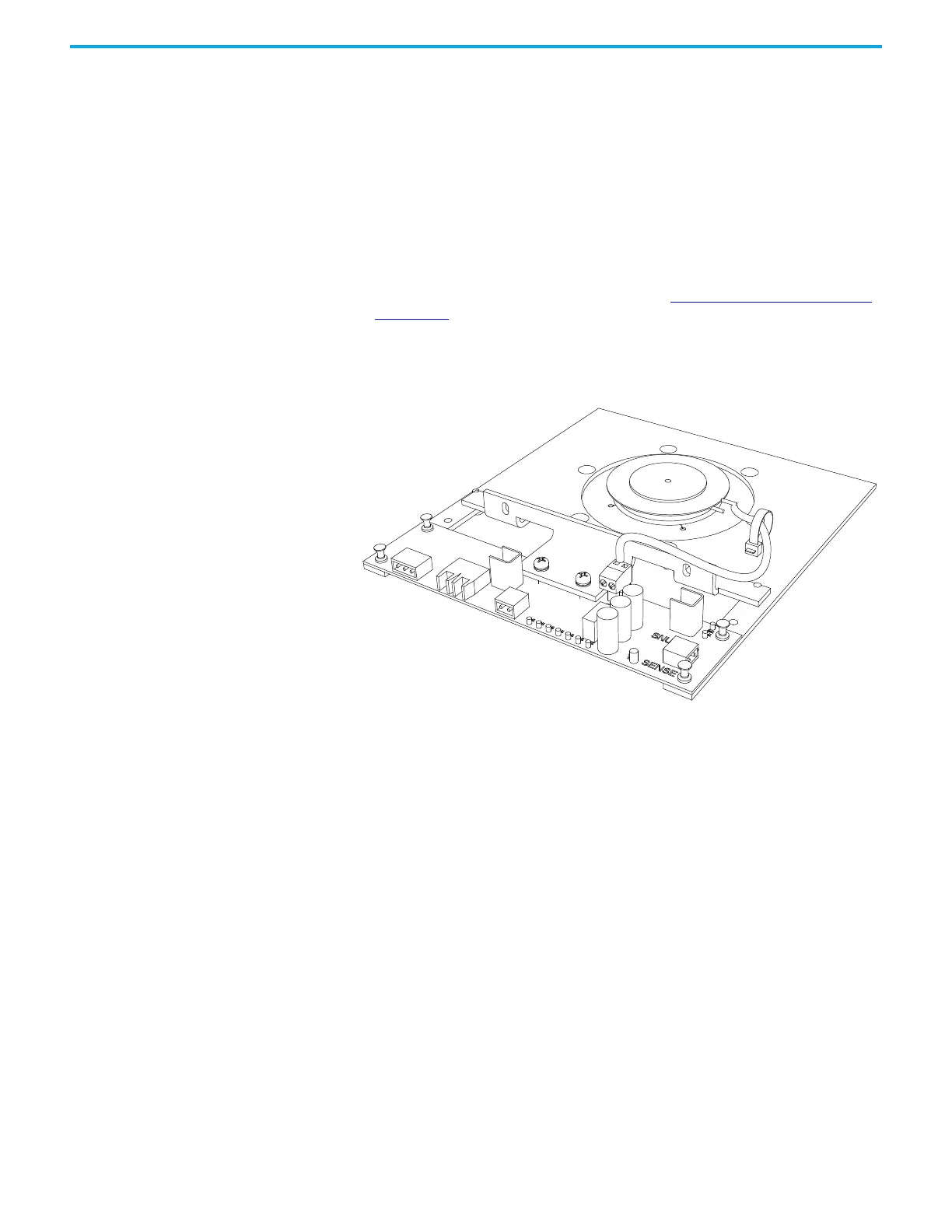
Figure 78 - SCR and SPGDB Assembly
 Loading...


