Rockwell Automation Publication 750-TG100B-EN-P - June 2019 119
Frame 7 Components Chapter 6
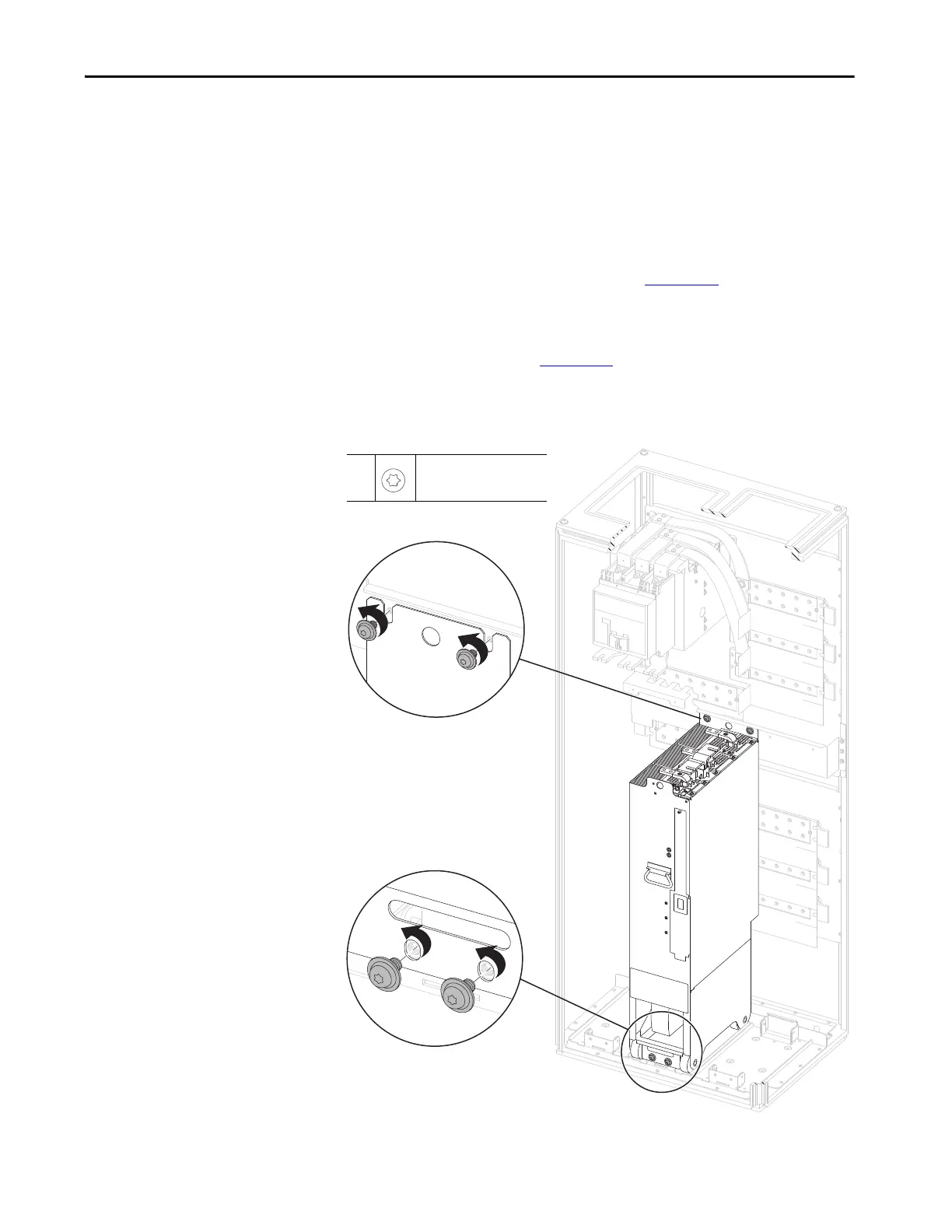
15. Remove the two M10 x 20 mm torx screws that secure the upper power
module chassis to the module support bracket.
16. Leave the two M10 x 20 mm screws that secure the power module chassis
to the floor mounting bracket while preparing the PowerFlex 750-Series
service cart or service ramp.
17. To remove the module by using the service cart, follow the detailed
instructions in the PowerFlex 750-Series Service Cart and DCPC Module
Lift Installation Instructions, publication 750-IN105
.
To remove the module using PowerFlex 755TM service ramp, follow the
procedures that are detailed in the PowerFlex 755T Module Service Ramp
Instructions, publication 750-IN108
.
18. To release the power module, remove the two remaining M10 screws.
19. Remove the power module from the enclosure.
15
15,
18
M10 x 20 mm
T45
19.8 N•m (175 lb•in)
18
 Loading...


