128 Rockwell Automation Publication 750-TG100B-EN-P - June 2019
Chapter 6 Frame 7 Components
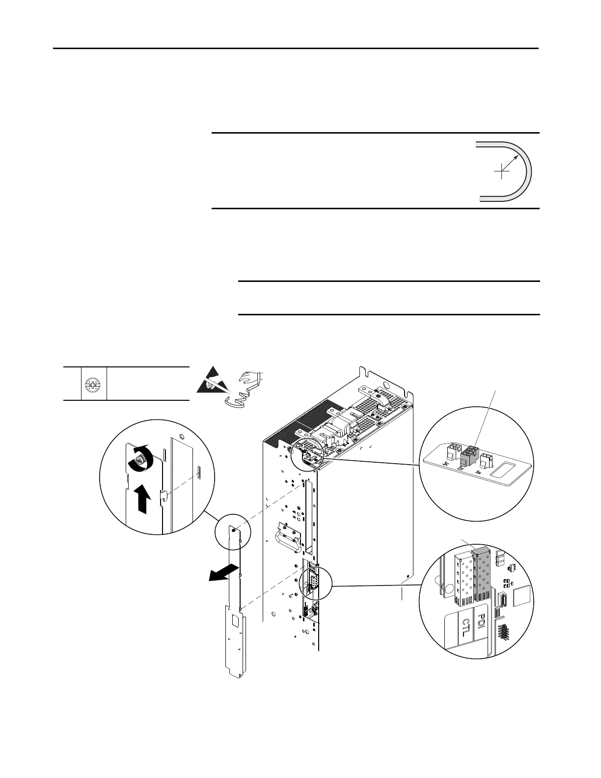
5. Loosen the thumbscrew that secures the connection cover to the front of
the line side converter power module.
6. Use the screw to lift the connections cover up and off the power module
chassis.
7. Without bending the cable to a radius less than 50 mm (2 in.), remove the
fiber-optic cable from the transceiver in the PDI port of the power
interface circuit board in the power module and remove the fiber-optic
cable from the power module chassis.
8. Disconnect the 24V DC signal wire harness connector P3 from J3 on the
I/O panel in the line side converter power module.
IMPORTANT
Minimum inside bend radius for fiber-optic cable is 50 mm
(2 in.). Any bends with a shorter inside radius can
permanently damage the fiber-optic cable. Signal
attenuation increases as inside bend radius is decreased.
IMPORTANT Observing the minimum bend radius, carefully coil the fiber optic cable
and secure it to the LCL filter module where it cannot be damaged.
8 (J3)
7 (PDI Fiber-optic Port)
5
–
P2 or F - 6.4 mm (0.25 in.)
1.8 N
•m (16 lb•in)
 Loading...


