130 Rockwell Automation Publication 750-TG100B-EN-P - June 2019
Chapter 6 Frame 7 Components
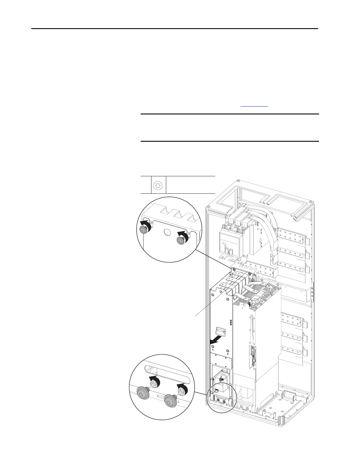
11. Remove the two M10 x 20 mm torx screws that secure the upper LCL
filter module chassis to the module support bracket.
12. Leave the two M10 x 20 mm screws that secure the LCL filter chassis to
the floor mounting bracket while preparing the PowerFlex 750-Series
service cart.
13. To remove the module by using the service cart, follow the detailed
instructions in the PowerFlex 750-Series Service Cart and DCPC Module
Lift Installation Instructions, publication 750-IN105
.
14. Remove the two remaining M10 screws at the bottom of the module, and
pull the module out only as far as necessary to expose the connections at
the back of the module.
IMPORTANT The AC fuse wire harness and 240V AC power wire harness connections
are on the back of the LCL filter module. These connectors must be
removed before you can release the module fully from the enclosure.
11,
14
M10 x 20 mm
T45
19.8 N•m (175 lb•in)
11
14
Fuse and 240V AC Power Harness
Connections at Back of Module.
Circuit Breaker AC Output Flexible Bus Bars
and Fuses Not Shown for Clarity Only.
 Loading...


