EasyManuals Logo

Rockwell Automation PowerFlex 755TL User Manual

Rockwell Automation PowerFlex 755TL
352 pages
To Next Page IconTo Next Page
To Previous Page IconTo Previous Page
Page #162 background imageLoading...
Page #162 background image
162 Rockwell Automation Publication 750-TG100B-EN-P - June 2019
Chapter 7 Control Bay and Control Pod Components
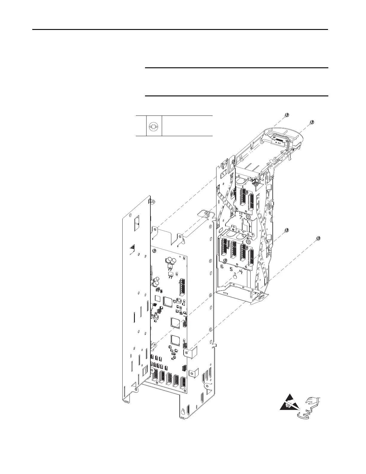
20. Remove the four M4 x 8-mm screws that secure the control pod chassis to
the standoffs on the control panel, then remove control pod chassis.
IMPORTANT The four M4 x 8-mm screws that secure the control pod chassis to the
control panel are not retentive. Take steps to be sure that the screws do
not fall into the drive below.
20
M4 x 8 mm
T20 or F - 6.4 mm (0.25 in.)
2.6 N
•m (23 lb•in)
=

Table of Contents

Questions and Answers:

Question and Answer IconNeed help?

Do you have a question about the Rockwell Automation PowerFlex 755TL and is the answer not in the manual?

Rockwell Automation PowerFlex 755TL Specifications

General IconGeneral
BrandRockwell Automation
ModelPowerFlex 755TL
CategoryDC Drives
LanguageEnglish

Related product manuals