Rockwell Automation Publication 750-TG100B-EN-P - June 2019 163
Control Bay and Control Pod Components Chapter 7
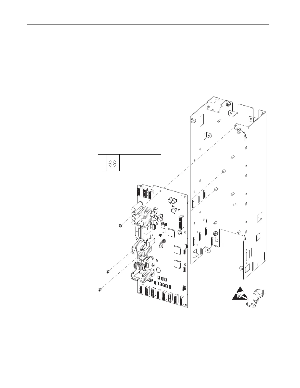
21. Remove the three M4 x 8-mm long screws that secure the fiber-optic
interface board to the control pod.
22. Move the fiber-optic interface board slightly upward toward top of the
control pod, so that keyholes on board clear the mounting posts and lift off
the board.
23. Rotate the left side of fiber-optic interface board away from the control
pod so that the board clears the mounting tab on right sidewall of the
control pod. Remove the board from the control pod.
21
M4 x 8 mm
T20 or F - 6.4 mm (0.25 in.)
2.6 N
•m (23 lb•in)
 Loading...


