280 Rockwell Automation Publication 750-TG100B-EN-P - June 2019
Chapter 9 Power Bay Components
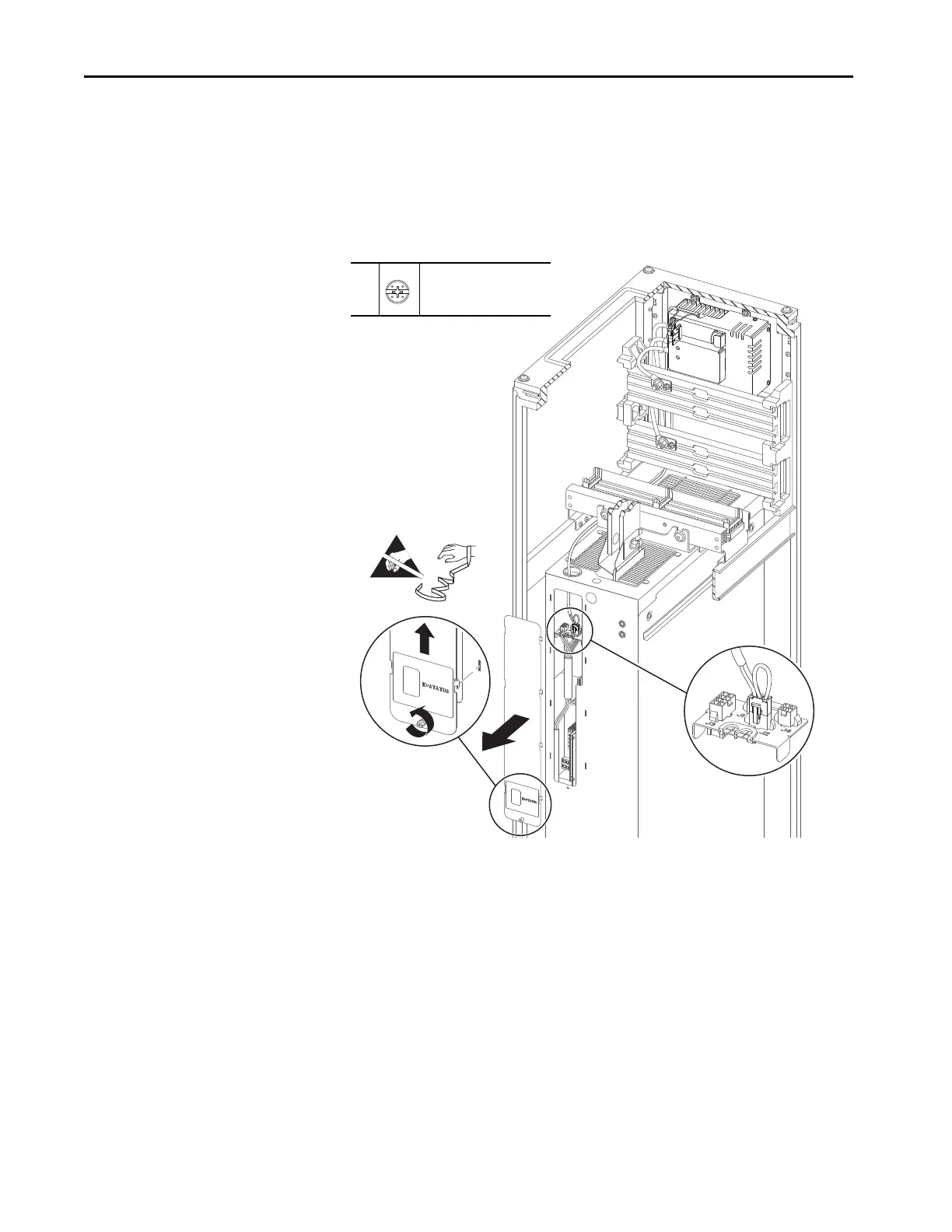
5. Loosen the thumb screw that secures the connections cover to the front of
the power module.
6. By using the screw, lift the connections cover up and off the power module
chassis.
7. Disconnect the DC bus conditioner cable connector P2 from J2 on the I/
O panel in the power module.
5
6
7
5
–
P2 or F - 6.4 mm (0.25 in.)
1.8 N•m (16 lb•in)
 Loading...


