BRP-Rotax
INSTALLATION MANUAL
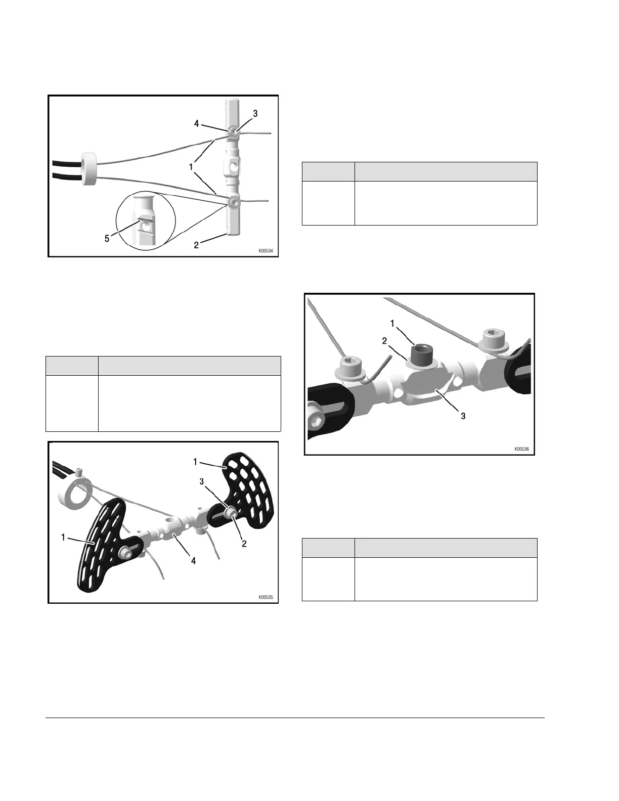
Figure 7.20
1 Bowden cable
2
Control whip
3 Allen screw
4
Washer
5
Oblique millings
Step
Procedure
12 Hand-tighten control lever left and right
(pos. 1) onto the control whip (pos. 4),
using M6 Allen screws (pos. 2) and
washers (pos. 3).
Figure 7.21
1 Control lever
2
Allen screw
3 Washer
4
Control whip
NOTE
The control lever can also be attached on the
back, depending on how it is more ergonomic
for the driver.
Step
Procedure
13
Install spacer (pos. 1) with washer
(pos. 2) onto the bottom side of the
control whip (3).
NOTE
The bottom side is, where the screws of the
Bowden cables are fixed.
Figure 7.22
1
Spacer
2
Thrust washer
3
Control whip
Step
Procedure
14 Tighten Allen screw M6x60 (pos. 1)
and washer (pos. 2) onto the top of the
control whip (pos. 3).
NOTE
Top is the opposite side, where the screws of
the Bowden cables are attached.
6
Page 10
Edition: September 01 2019
Effectivity: 125 MAX DD2 evo

 Loading...


