7
Introducing the ZoneFlex Wireless Bridge
Get to Know the Hardware Features
LED Colors and What They Mean
The ZoneFlex 7731 Wireless Bridge includes 6 dual color LEDs. The LEDs function in two
modes, normal operation mode and aiming mode.
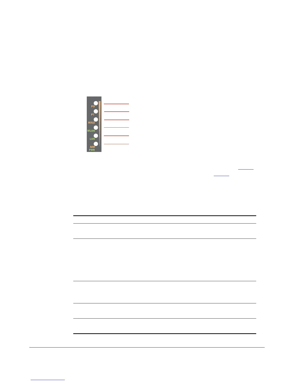
Figure 4. LED Indicators
■ For Normal Operation Mode LED states and what they indicate, refer to Ta ble 2.
■ For Aiming Mode LED states and what they indicate, refer to Ta ble 3.
Normal Operation Mode
In Normal Operation Mode, the WLAN LED indicator is off when disconnected, flashing
green while connecting and solid green when a connection has been established.
Table 2. Normal Operation Mode LED indicators
LED Meaning
LED 1 (AIM/PWR) Solid Green = Power on
Off = Power off
LED 2 (LAN) Solid (Green / Orange / Yellow) = Link Up
Blinking (Orange / Green) = Activity
Off = Link Down
Green = Gigabit Ethernet (10/100/1000) full/half duplex
Orange = Fast Ethernet (10/100) full/half duplex
Yellow = Ethernet full/half duplex
LED 3 (WLAN) Solid Green = Associated
Blinking Green = Not Associated
Off = Radio Off
LED 4 (ROLE) Solid Yellow = This unit is the Root Bridge
Off = This unit is the Non-Root Bridge
LED 5 & 6 (P0 and P1) Alternating Blinking = Provisioning in process, role is unknown
Simultaneous Blinking = Provisioning complete; reboot pending
LED 1
LED 2
LED 3
LED 4
LED 5
LED 6