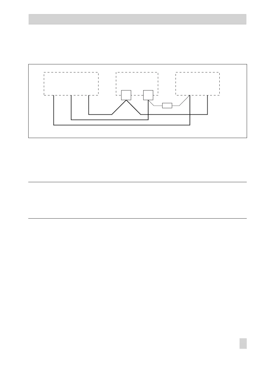
Connecting the water flowmeter (order no. 1400-9246)
A power supply unit and a 4.7 k
Ω
resistor are required for the water flowmeter to function.
Connecting the actuators
4
Three-step or on/off outputs:
Connect cables with at least 1.5 mm² suitable for damp locations to the terminals of the
controller output. The direction of travel needs to be checked at start-up.
Note!
Electric actuators are not automatically supplied with a voltage by the controller. They can be
connected to an external voltage source over the terminals 25 or 28.
If this is not required, place a jumper from terminal 18 to terminal 25 and 28.
Connecting the pumps
Connect all cables with at least 1.5 mm
2
to the terminals of the controller as illustrated in the
wiring diagram.
Legend for wiring diagrams:
AF Outdoor sensor BE Binary input
FG Potentiometer BA Binary output
RF Room sensor Rk Control circuit
RüF Return flow sensor UP Circulation pump
SF Storage stank sensor SLP Storage tank charging pump
VF Flow sensor WMZ Heat meter
EB 5575 EN 97
Electrical connection
4.7 kΩ
+
_
03
TROVIS 5575Water Flowmeter Power supply unit
4.5 ... 24 V DC
13
brown/
black
greenwhite