7. Electrical installation
Installer reference guide / Mono tank integrated type 98
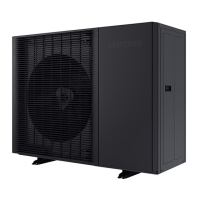
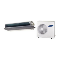
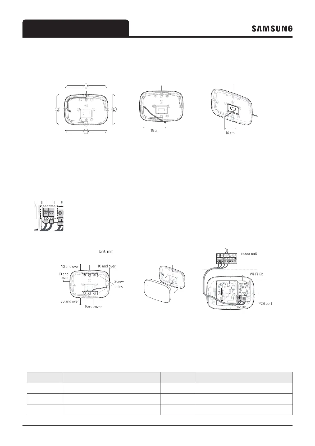
2 Arrange the power and communication cables along the back cover.
<Wires installed on the wall> <Wires installed in the wall>
If necessary, remove
this part to secure more
space for wiring.
3 Use two or more screws to fix the back cover to the wall. Connect the power cables (V1, V2) and communication cables
(F1, F2) to the terminals on the back of the front cover while adjusting them to a suitable length.
4 When connecting the power cables to V1 and V2, fasten the PCB terminal screws (CN5) to a torque of 0,6Nm or less.
Screw size : M3 x 6
least 10 mm (up/right/left) and
50 mm (down) around the back
cover before fixing the back
cover on the wall
screw holes.
PCB terminal.
①
②
④
⑤ ⑥
③
Item Contents Item Contents
①
Power/Communication terminals
④
LED
②
Tracking/Reset button
⑤
Network PBA
③
Micro SD card slot
⑥
Interface module PBA