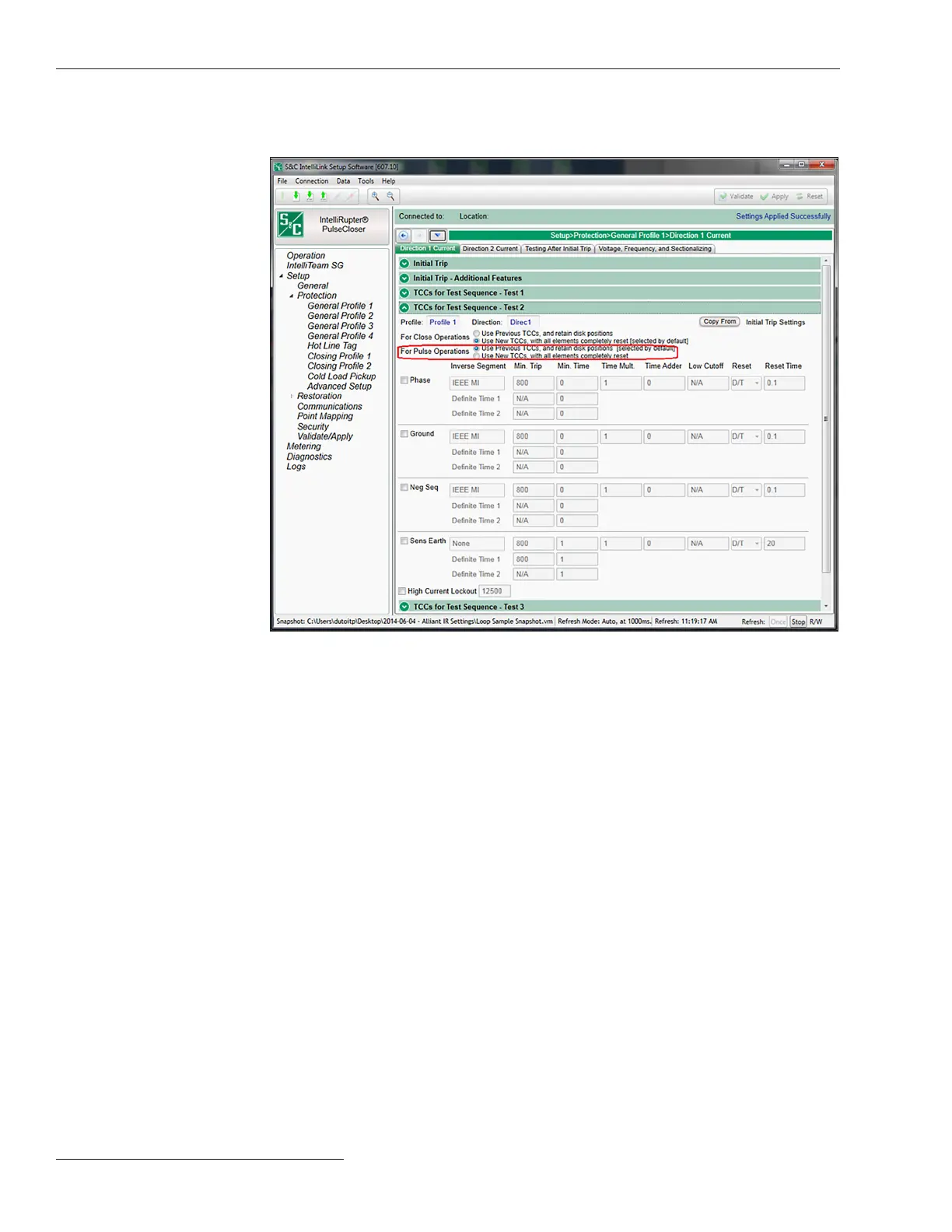
Figure 73. The PulseFinding technique setpoint on the Setup>Protection>General Profile 1>
Direction 1>Current>Initial Trip - Additional Features screen for Test 2.
STEP 9. Adjust the Overcurrent and IFS elements on the Testing After Initial Trip
screen. See Figure 74 on page 131.
(a) The Overcurrent Trip element can be 1-Phase Trip or 3-Phase Trip
mode as congured by the Initial Trip drop down menu selection.
(b) The Delay setpoint is the time interval between tests.
(c) When Pulse mode is selected for the O/C Sequence setpoint, the
IntelliRupter fault interrupter will use PulseClosing Technology to test the
line for each programmed test.
(d) Congure an appropriate time for the O/C and IFS Sequence Reset Time
setpoint. This is the duration after the IntelliRupter fault interrupter has
successfully closed during a test sequence (test 1 or test 2) until it resets to
the Initial Trip state.
(e) Congure the Retain Source-Side for Test Sequence mode to the Yes
state. This feature prevents backfeeding a substation as the result of a
restoration event returning voltage from the opposite side while the
IntelliRupter fault interrupter has lost source voltage and is still running
the test-sequence procedure.
STEP 8. Congure the Test 2 TCC Curves setpoint. Congure TCC curves for both
Direction 1 and Direction 2. See Figure 73.
130 S&C Instruction Sheet 766-530
Loop Restoration
 Loading...


