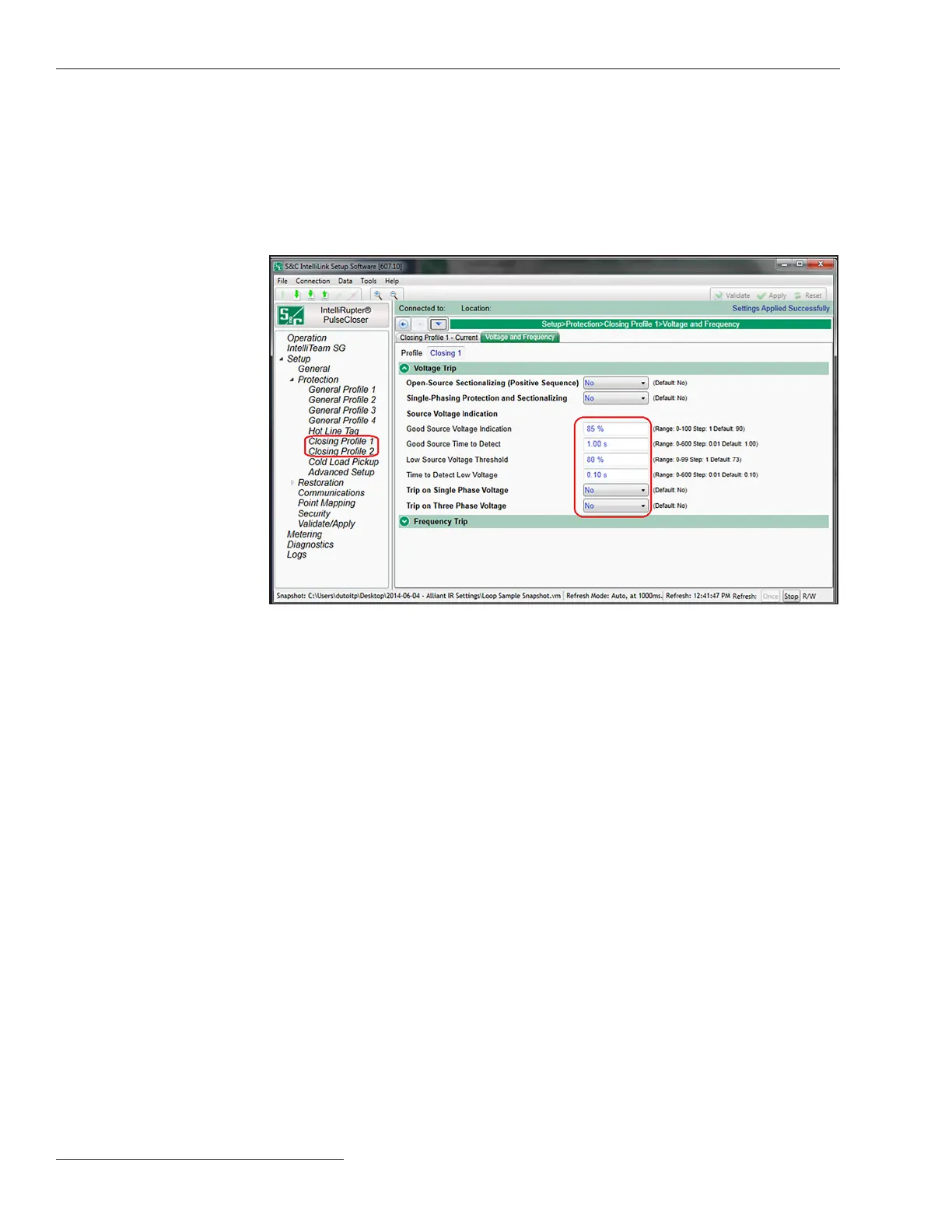
Figure 78. The Setup>Protection>Closing Profile 1>Voltage and Frequency>Voltage Trip
screen.
Follow these steps to congure the Loop Restoration mode for a normally open feeder
conguration:
STEP 1. On the Setup> Restoration>Loop screen, enable the Enable Loop Restoration
setpoint for the desired General Prole. See Figure 76 on page 132.
STEP 2. Select the direction(s) that will use Loop Restoration mode with the Direction
setpoint on the Setup>Restoration>Loop screen.
STEP 3. Select the Open state for the Normal State setpoint on the Setup>Restoration>
Loop screen.
When Loop Restoration mode is making a decision to close and restore the feeder,
it uses the profile and test sequence programmed at the Setup>Restoration>Loop>Loop
Restoration Test Sequence screen. See Figure 76 on page 132.
If voltage is lost on either side of the IntelliRupter fault interrupter for the configured
Time Delay Before First Test setpoint and the IntelliRupter fault interrupter is in the
Loop Restoration mode Ready state, it will close.
Note: Voltage must also be below the Backfeed Voltage Level setpoint for Loop
Restoration mode to qualify it as a voltage loss. This setpoint is on the General>
Site-Related>System screen. The default value is 10%. See Figure 6 on page 19. If volt-
age goes above the Backfeed Voltage Level setpoint while timing on the Time Delay
Before First Test setpoint, this timer is reset.
Normally Open
Configuration
There are two closing profiles; the second closing profile can be initiated by
SCADA, an IntelliLink command, or by pulling down on the manual CLOSE lever
twice. In most cases, the second closing profile is setup to not use PulseClosing
Technology when closing (hard close).
STEP 13. Match the Voltage Indication settings in the General Prole mode for both
Closing Prole 1 and Closing Prole 2 modes. See Figure 78.
134 S&C Instruction Sheet 766-530
Loop Restoration

 Loading...


