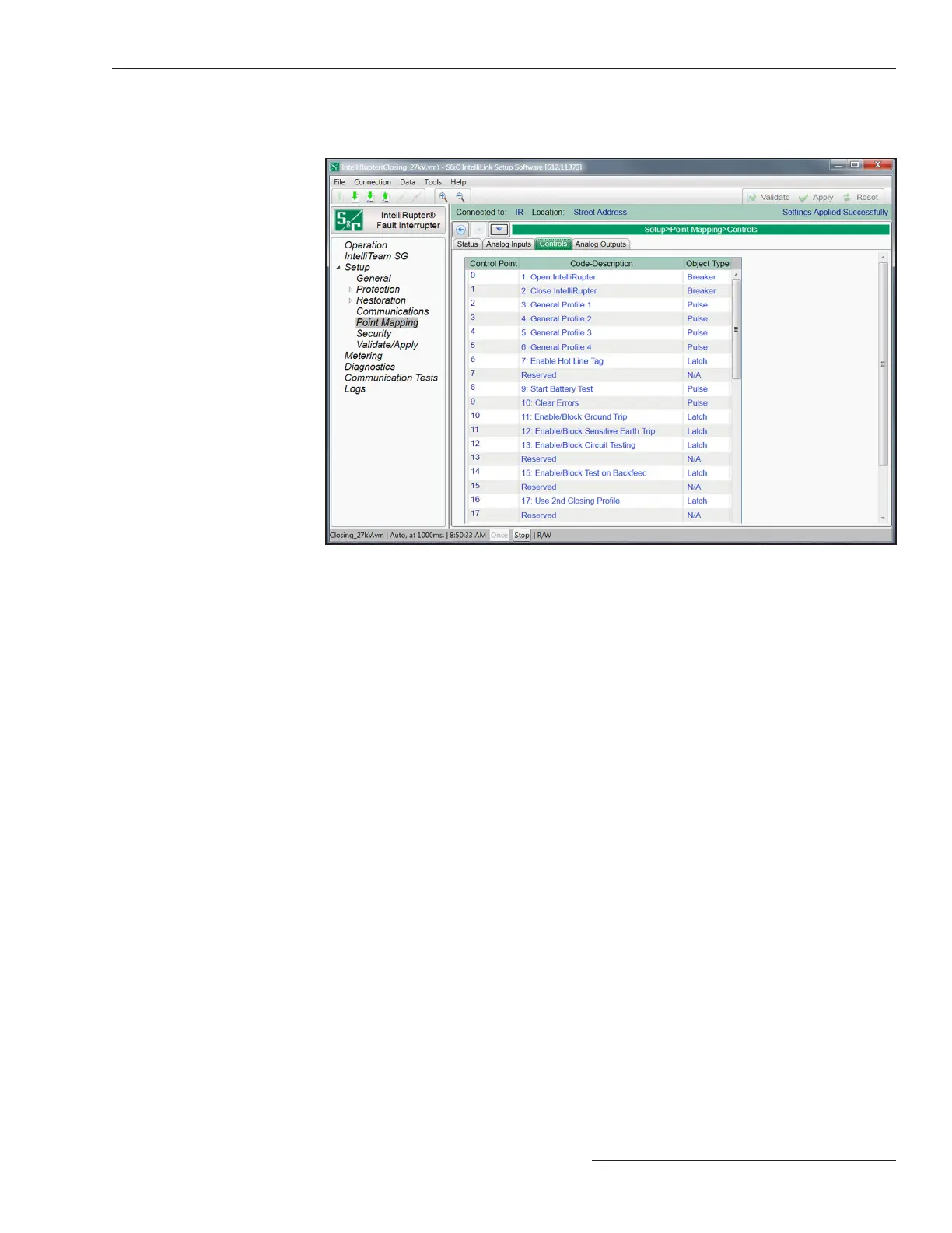
Figure 99. The Setup>Point Mapping>Control Points screen.
Control Point
This is the point number the SCADA system will use when operating the control point.
Code-Description
These are the point codes representing specic control points that may be assigned to
individual SCADA point numbers. Setting a code-description to the End option denes
the end of the congured points list and the maximum number of control points that
can be returned.
Object Type
This species the type of control code the SCADA master will use in the control relay
output block request. Specify the Breaker option for a Trip/Close operation, the Latch
option for a Latched On/Off operation, the Pulse option for a momentary control output,
or the N/A option if the control point will not be used. The object type must be valid for
the selected object. For more information see Instruction Sheet 766-560, “IntelliRupter®
PulseCloser® Fault Interrupter: DNP Points List and Implementation.” The control
operation will be rejected if the object type received is a Pulse object type received and
there is either a Breaker or Latch mapped object type, or if there is a Pulse mapped
object type and either a Breaker or Latch object type is received.
Every control point configured for Breaker accepts Latch operations, and every
control point configured for Latch accepts Breaker operations.
Function Code
Control requests may be issued using the Select/Operate sequence, the Direct Operate,
and Direct Operate No Ack function codes.
The screen shown in Figure 99 has configuration parameters for control point
mapping. Map these points to make them available in your SCADA system.
DNP Control Points
S&C Instruction Sheet 766-530 167
Communication Setup

 Loading...


