• To restore the Loop Restoration mode Ready state, the IntelliRupter fault
interrupter must be manually closed with the OPEN/CLOSE/READY lever or a Wi-Fi
or SCADA command, and the Loop Restoration mode must be enabled with a Wi-Fi
or SCADA command.
• If Automatic Enable of Loop Restoration for Manual Lever Close mode (only
applicable to Normally Closed conguration) has been congured, then the Wi-Fi or
SCADA command to re-enable the Loop Restoration mode is not necessary. When
the IntelliRupter fault interrupter is manually closed, it will go to the Ready state if
the other conditions for a Loop Restoration mode Ready state have been satised.
The Loop Restoration Test sequence uses this procedure:
• If there is no voltage on both sides during a Closing Profile command, the
command is rejected, and the timers and sequence continue as though the close
attempt detected a fault.
• When a Closing Prole command is blocked because of a sync check result, the
timers and sequence continue as though the close attempt detected a fault.
• When the IntelliRupter fault interrupter is in the Open state and voltage returns
to both the X and Y sides or voltage is lost on both the X and Y sides, the Loop
Restoration Test sequence is suspended and the Maximum Time Allowed for
Restoration Timer continues. If voltage returns to one of the terminals, the test
sequence is resumed. When the Maximum Time Allowed for Restoration Timer
expires, Loop Restoration mode is disabled. The only exception is if the IntelliRupter
fault interrupter is closed, it may enter the Loop Restoration mode Ready state if
all other conditions are met.
• A manual command to change proles by either the OPEN/CLOSE/READY lever or
a Wi-Fi or SCADA command that occurs during the test sequence, this takes Loop
Restoration mode out of the Ready state, and all timers will stop and reset. Manual
actions are required to return Loop Restoration mode to the Ready state.
These steps describe the procedure to use the Loop Sample Snapshot.vm le with
IntelliLink Ofine software to create a custom settings template for Loop Restoration
mode.
STEP 1. Start the IntelliLink Ofine software by clicking on the IntelliLink Ofine
software icon. See Figure 65.
Loop Restoration
Configuration
Example
Figure 65. The IntelliLink Offline software icon.
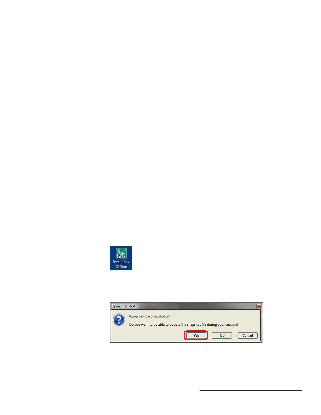
STEP 2. Open the Loop Sample Snapshot.vm le. In the Open Snapshot dialog box, click
on the Yes button to allow le modication. See Figure 66.
Figure 66. The Open Snapshot dialog box.
S&C Instruction Sheet 766-530 125
Loop Restoration

 Loading...


