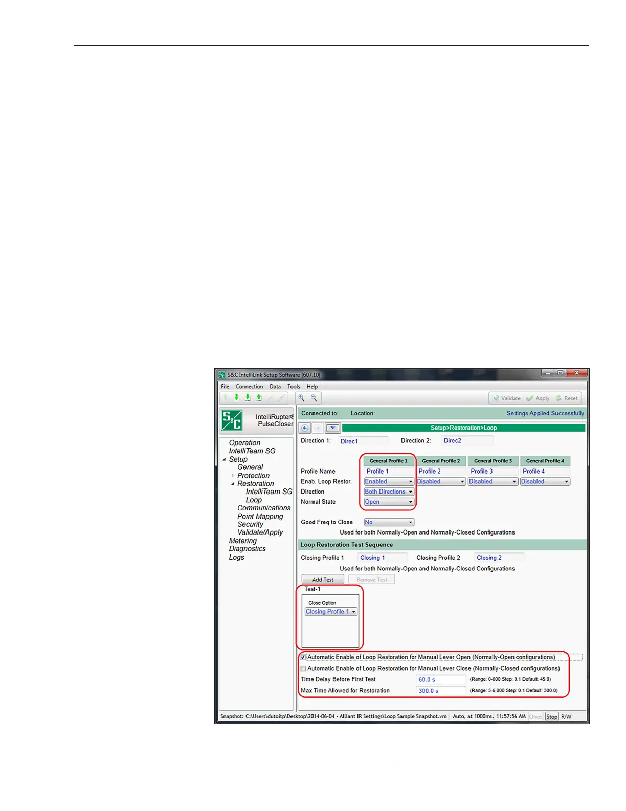
Figure 79. The Setup>Restoration>Loop screen.
Follow these steps to congure the Loop Restoration mode for a normally closed feeder
conguration:
STEP 1. On the Setup> Restoration>Loop screen, enable the Enable Loop Restoration
setpoint for the desired General Prole. See Figure 79.
STEP 2. Select the direction(s) that will use Loop Restoration mode. Congure the
Direction setpoint on the Setup>Restoration>Loop screen.
STEP 3. Select the Closed state for the Normal State setpoint on the Setup>
Restoration>Loop screen.
When Loop Restoration mode is making a decision to close and restore the feeder,
it uses the profile and test sequence programmed at the Setup>Restoration>Loop>Loop
Restoration Test Sequence screen. See Figure 79.
If the IntelliRupter fault interrupter tripped open for the Voltage Trip element and
then voltage returns to either side for the configured Time Delay Before First Test
setpoint, and the IntelliRupter fault interrupter is in the Loop Restoration mode Ready
state, it will close.
Normally closed loop devices do not use the Time Delay Before First Test setpoint.
They decide when to close based on the Good Source Voltage Indication setpoint,
configured in Step 10 on page 131.
Note: Voltage must also be below the Backfeed Voltage Level setpoint on one
side for Loop Restoration mode to close. This setpoint is on the Setup>General>
Site-Related>System screen. The default value is 10%. See Figure 6 on page 19. If
voltage goes above the Backfeed Voltage Level setpoint while timing on the
Time Delay Before First Test setpoint, this timer is reset.
Normally Closed
Configuration
S&C Instruction Sheet 766-530 135
Loop Restoration

 Loading...


