EasyManuals Logo

S&C IntelliRupter PulseCloser User Manual

S&C IntelliRupter PulseCloser
181 pages
To Next Page IconTo Next Page
To Previous Page IconTo Previous Page
Page #136 background imageLoading...
Page #136 background image
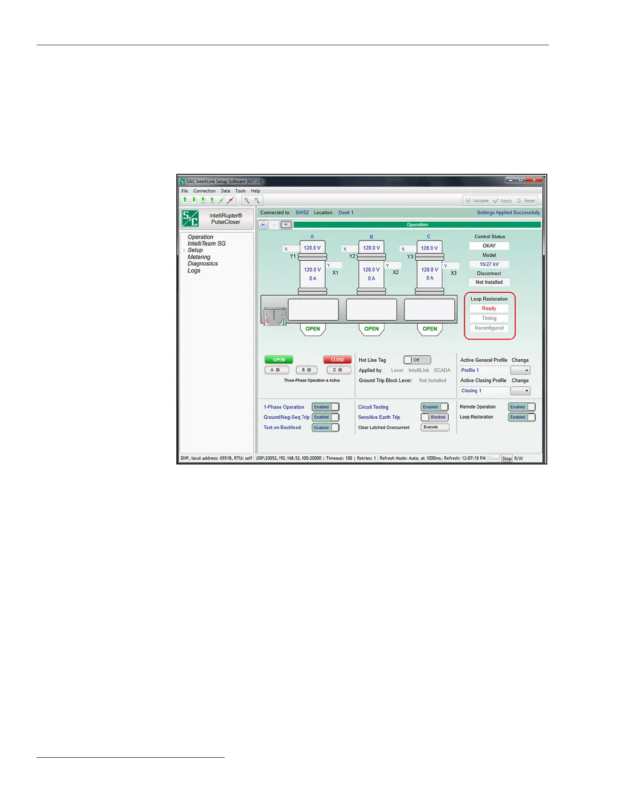
Figure 80. The Operation screen displays the Ready state in the Loop Restoration status
indicator.
The following indicators show Loop Restoration mode is in the Ready state:
The Operation screen shows the Ready state in the Loop Restoration state indica-
tor. See Figure 80.
The control module STATUS indicator blinks three times every 30 seconds to indicate
the Ready state is active. See Figures 81 and 82 on page 137.
The Loop Restoration Ready DNP Status Point is set when the Ready state is active.
See Figure 80.
136 S&C Instruction Sheet 766-530
Loop Restoration

Table of Contents

Other manuals for S&C IntelliRupter PulseCloser

Questions and Answers:

Question and Answer IconNeed help?

Do you have a question about the S&C IntelliRupter PulseCloser and is the answer not in the manual?

S&C IntelliRupter PulseCloser Specifications

General IconGeneral
BrandS&C
ModelIntelliRupter PulseCloser
CategoryIndustrial Electrical
LanguageEnglish

Related product manuals