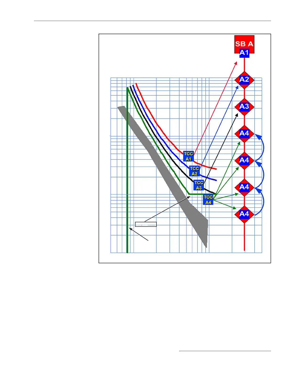
Fault Magnitude
T
i
m
e
Pickup setting of
the slowest
IntelliRupter fault interrupter
100 ms
Figure 17. TCC curves and communication-enhanced coordination.
This example where IR represents an IntelliRupter Fault interrupter shows
communication-enhanced coordination for a temporary fault.
• All IntelliRupter fault interrupters are closed and coordinated where possible.
See Figure 18 on page 36.
• IntelliRupter fault interrupters IR3 and IR4 detect the fault and send curve-shift mes-
sages to their source-side neighbors. See Figure 19 on page 36.
• IR2 and IR3 shift to a slower TCC curve. See Figure 20 on page 36.
• IR4 trips and begins testing. See Figure 21 on page 36.
• The temporary fault at IR4 clears and IR4 recloses and sends an Event Done message
to the other CEC-coordinated IntelliRupter fault interrupters.
• IR2 and IR3 change back to the original TCC curves. See Figure 22 on page 36.
CEC Example for a
Temporary Fault
S&C Instruction Sheet 766-530 35
Communication Enhanced Coordination

 Loading...


