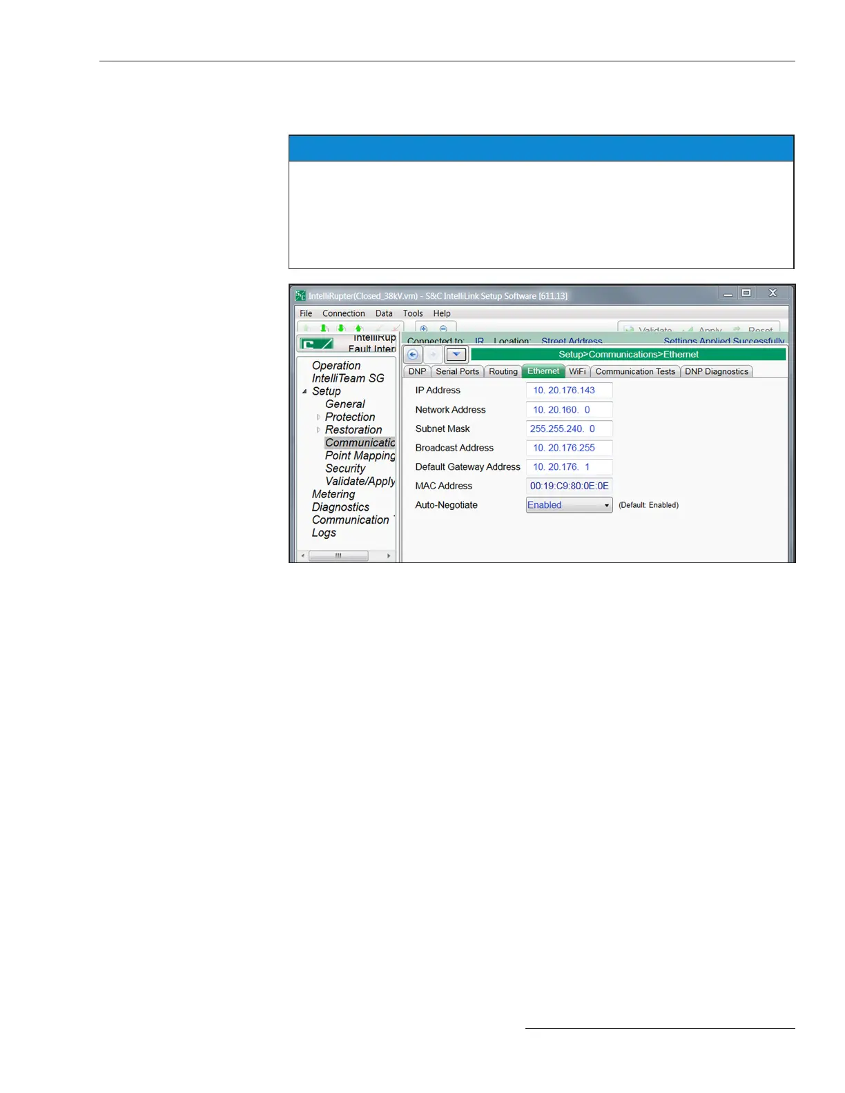
Figure 91. The Setup>Communications>Ethernet screen.
IP Address
This is the IP address of the control.
Network Address
This is the IP address of the network. The IP address entered must be an address within
the network. The relationship between the IP address entry and the network address
entry is dened by the subnet mask entry.
Subnet Mask
This is a 32-bit mask that divides an IP address into subnets and species the available
hosts. Two bits are always automatically assigned. For example, in 255.255.255.0, “0” is
the assigned network address; and in 255.255.255.255, “255” is the assigned broadcast
address. The “0” and “255” are always assigned and cannot be used.
IntelliRupter fault interrupters with the R3 control have two Ethernet ports—
Ethernet 1 and Ethernet 2. See Figure 91.
NOTICE
Ethernet 2 is reserved for future applications. When new functionality is implemented
it will only be used with IntelliRupter fault interrupters shipping on or after
May 6, 2020 with an SDA-4540R3 control installed.
The default Ethernet 2 IP address is 192.168.2.1. The subnet is configured for
subnet 192.168.2.0 /24. If necessary change this configuration to avoid conflicts
with other subnets used on the network.
Ethernet
S&C Instruction Sheet 766-530 153
Communication Setup

 Loading...


