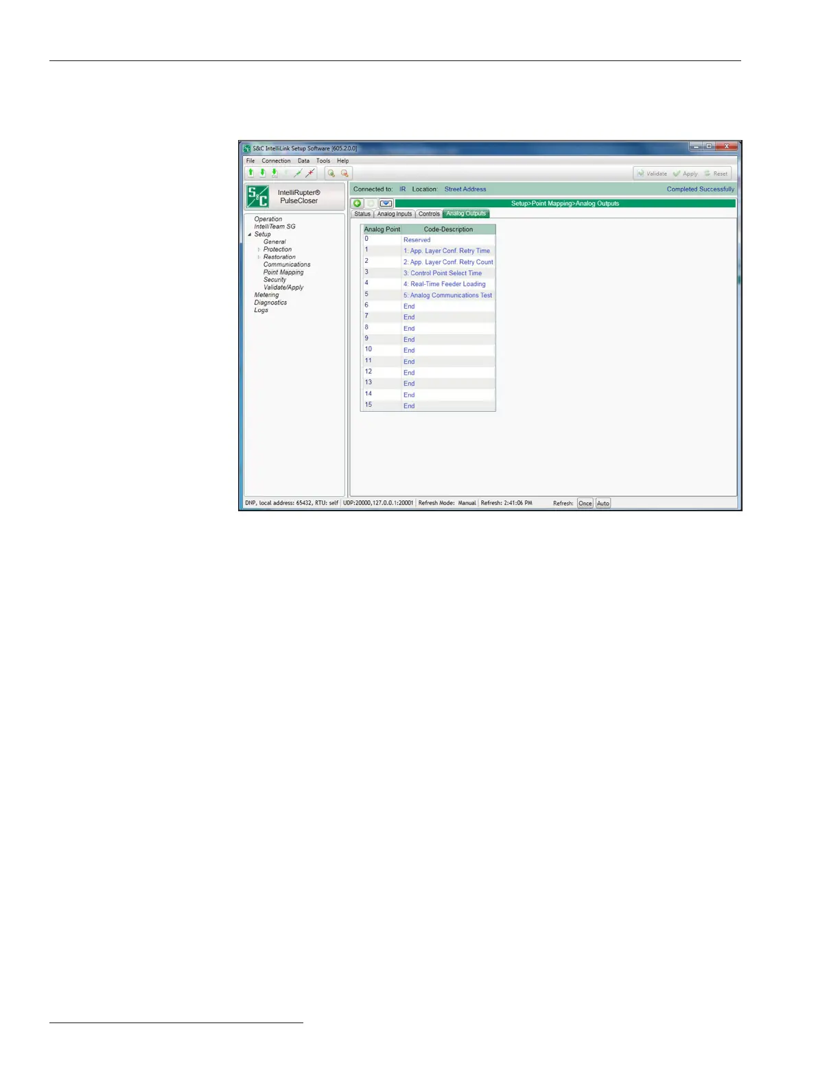
Figure 100. The Setup>Point Mapping>Analog Output Points screen.
Analog Point
This is the point number the SCADA system will use when operating the analog output
point.
Code Description
These are the point codes representing specic analog outputs that may be assigned to
individual SCADA point numbers. Setting a Code-Description to the End option denes
the end of the congured points list and the maximum number of analog output points
that can be returned.
The screen shown in Figure 100 has conguration parameters for analog output points.
Map these points to make them available in your SCADA system.
DNP Analog Output
Points
168 S&C Instruction Sheet 766-530
Communication Setup

 Loading...


