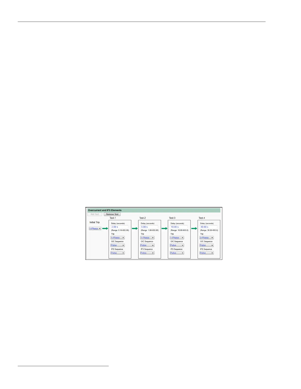
Figure 47. The Setup>Protection>General Profile 1>Direction 1 Current>Testing After Initial
Trip>Overcurrent and IFS Elements screen.
Overcurrent and IFS (Intelligent Fuse Saving) Elements
Number of Tests
Specify the number of tests to be performed (up to four) by clicking on the Add Test or
Remove Test button.
Initial Trip: 1-phase or 3-phase
This setting selects either a 1-Phase or 3-Phase Trip operation for overcurrent
events related to the Base O/C and Intelligent Fuse Saving elements. Each test can
be independently congured for either 1-Phase or 3-Phase operation. The last test
conguration denes whether a Single-Phase or Three-Phase Lockout state will be
used. The 3-Phase mode is the default.
When the IntelliRupter fault interrupter is set for 1-Phase mode and responds to an
overcurrent event, any phase that has timed beyond 20% of trip will be tripped. If the
Three-Phase Trip for Multiple Phase Faults setting has been set to the Yes option
and more than one phase has timed beyond 20%, all phases will be tripped. When set for
3-Phase mode, all three phases trip. When the IntelliRupter fault interrupter is set for
1-Phase mode and responds to a ground overcurrent event, any phase picked up will
be tripped. If none of the phases have picked up or if Three-Phase Trip for Multiple
Phase Faults setting has been set to the Yes option and more than one phase has picked
up, all phases will be tripped. When set for 3-Phase mode all three phases trip.
The Operation screen fault flags indicate which phases have been involved in an event.
The fault flags are also communicated as DNP Status Points described in Instruction
Sheet 766-560, “IntelliRupter® PulseCloser® fault interrupter: DNP Points List and
Implementation.”
A fault flag is set in response to an Overcurrent event for any phase that has timed
beyond 20% of trip when an Overcurrent element has tripped or for any phase that
was timing when a Ground Overcurrent element tripped. If a Ground Overcurrent
element trips and none of the phases are picked up, a fault flag will be set for each phase.
See Figure 47.
Test-1 Delay, Test-2 Delay, Test-3 Delay, Test-4 Delay
Specify the open time (in seconds) between each test. (Minimum: 0.18 for
Time-1, 1.80 for Time-2, 10.00 for Time-3, and 30.00 for Time-4; Maximum: 655.00;
Increment: 0.01.)
74 S&C Instruction Sheet 766-530
Protection Setup

 Loading...


