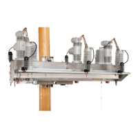
PulseClosing Technology Enabled
When set to Yes mode, an operation using PulseClosing Technology will be performed
before executing the closing prole to determine whether a fault is present. When a fault
is detected, the IntelliRupter fault interrupter will not complete the closing operation
and the line will not be subjected to damaging fault current. The Yes mode is typically
selected for the rst Closing Prole operation, and the No mode is selected for the
second Closing Prole operation.
Time for Closing Profile to be Active
This is the time (in seconds) the closing prole remains active after the commanded poles
have closed. The assigned general prole will be active after this timer expires when no
elements in the closing prole are picked up and timing. The TCC section of this prole
should be set to coordinate with upstream devices while this prole is active. The timer
starts after the last commanded pole is closed. (Range: 0.0-600.0; Step: 0.1; Default: 2.0)
Time for External Lever Closing Delay
When the OPEN/CLOSE/READY lever is operated, this timer must expire before the
Close operation starts. This delay does not apply to Wi-Fi or SCADA closing commands.
When this timer is set to 0 seconds, the second Closing Prole operation cannot be
set by the IntelliRupter fault interrupter OPEN/CLOSE/READY lever. (Range: 0.0-60.0;
Step: 0.1; Default: 5.0)
Sync Check Enabled
The No setting is the default for both closing proles. Typically, the Yes setting is selected
for the rst Closing Prole operation and the No setting is selected for the second
Closing Prole operation.
Voltage Difference Threshold
This is the percentage voltage difference between the X and Y sides above which a Close
operation is prevented. (Range: 5-50; Step: 1)
Phase Angle Difference Threshold
This is the phase-angle difference (in degrees) between the X and Y sides above which
a Close operation is prevented. (Range: 3-30; Step: 1)
Frequency Difference Threshold
This is the frequency difference (in hertz) between the X and Y sides above which a Close
operation is prevented. (Range: 0.1-1.0; Step: 0.1)
Voltage Threshold
This is the phase-voltage level below which a Synch Check operation will not be
performed. The Synch Check mode is active when all phase voltages are above this
congured level. (Range: 5-95; Step: 1)
S&C Instruction Sheet 766-530 99
Protection Setup

 Loading...