10 S&C Instruction Sheet 461-509
Mounting, Powering, and Securing the Communications Gateway
● A user-supplied disconnect switch may be required for installation between the ac input and the
PS/Battery board. Contact the nearest S&C Sales Office for details. See the power system diagram
(Figure 76 on page 84).
Follow these steps to power the communications gateway:
STEP 1. Remove the red protection cap attached to the power-connection terminal at
the bottom of the communications gateway.
STEP 2. Open the box.
STEP 3. Run the ac power cable down the pole. The unterminated end of the cable
should be connected to the overhead transformer.
STEP 4. Align the ve-pin connector at the terminated end with the notch of the power
connection terminal, make the connection, and tighten the ring. See Figure 2
on page 9.
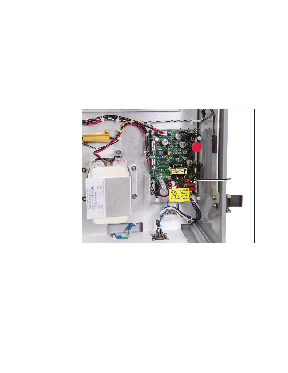
STEP 5. After a short delay, LEDs on the PS/Battery Board and the gateway controller
should light up, indicating the communications gateway is receiving power. See
Figure 1 on page 8 and Figure 3.
LED light
on PS/
Battery
Board
Figure 3. The communications gateway control PS/Battery Board.
Powering the
Communications
Gateway
●

 Loading...


