14 S&C Instruction Sheet 461-509
Installing and Replacing a Backup Battery
A backup battery to support the loss of control power and the gang operation feature,
if specified, is furnished factory-installed in the communications gateway. For
customers who initially choose not to have a backup battery, a backup battery system kit
(903-002460-01) can be retro tted to the communications gateway. See Figure 5 and
Figure 6 on page 15.
Follow these steps to install the battery in the communications gateway:
STEP 1. Disconnect the ac power cable connected to the bottom of the gateway and
then disconnect the ac-line fuse located at the lower right corner of the gateway
box.
STEP 2. Install the battery. The battery kit includes a battery, a top bracket, and
hardware.
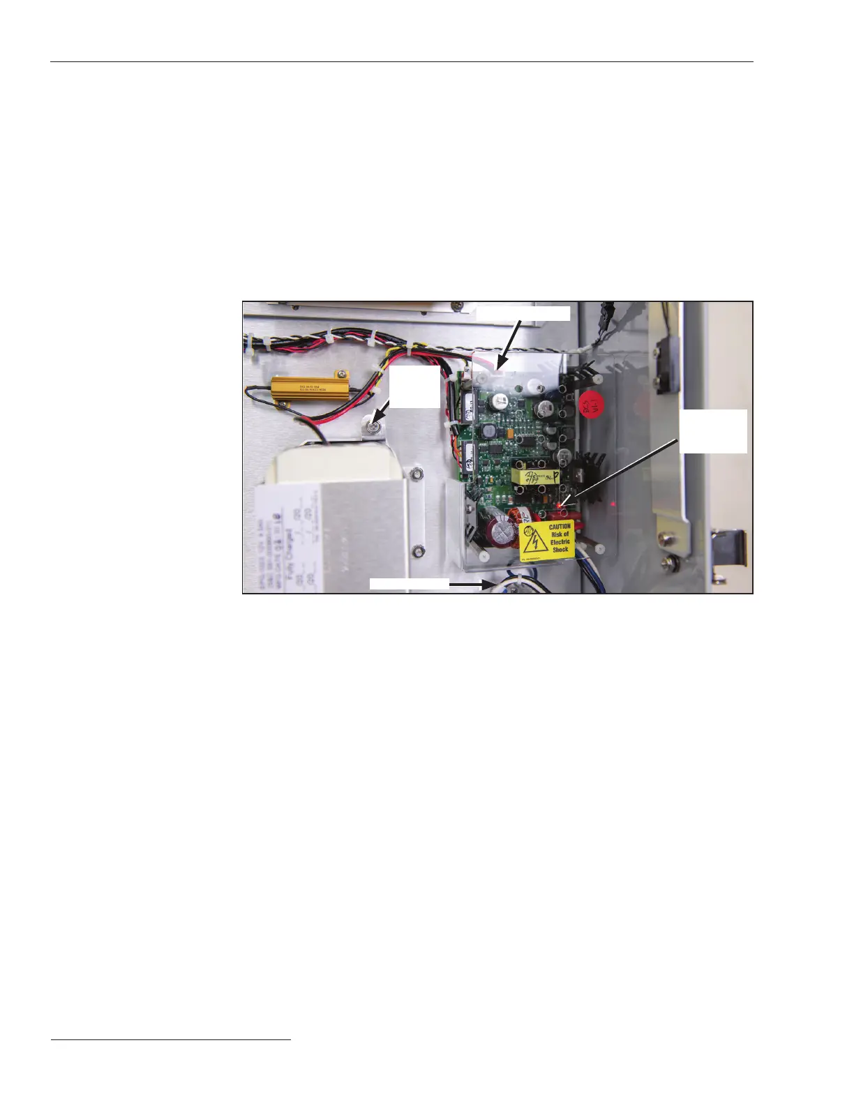
Figure 5. Disconnect the Ac line fuse and install the battery.
LED light on
PS/Battery
Board
2-pin connector
Ac line fuse
Spring-
loaded
screw
(a) The battery should be installed in the lower-middle section of the gateway.
(b) Install the battery using the two spring-loaded screws, with the connector
facing outward on top.
(c) Install the top bracket using the four nuts.
STEP 3. Connect the battery.
With the ac line fuse still removed, connect the red and black battery leads
to the white 2-pin connector on the PS/Battery board. The acrylic safety cover
over the PS/Battery board does not need to be removed to make this connection.
STEP 4. Replace the ac line fuse located at the lower right corner of the gateway box and
leave the ac cable connector disconnected.
STEP 5. Check the LEDs on the green gateway controller. After a short delay, LEDs on
the gateway controller should light up. This indicates the battery is functioning.
STEP 6. Reconnect the ac-cable connector.
Installing a New
Battery

 Loading...


