S&C Instruction Sheet 461-509 9
Mounting, Powering Up, and Securing the Communications Gateway
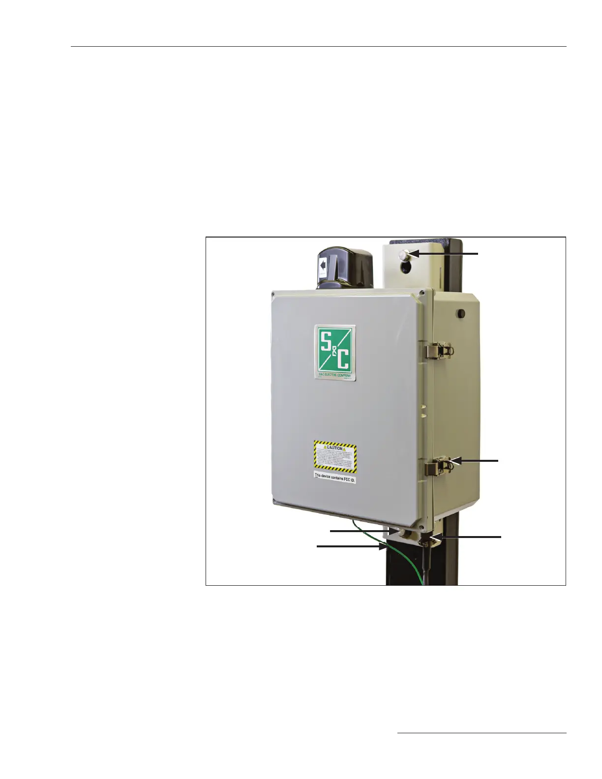
Follow these steps to mount the communications gateway:
STEP 1. Attach the communications gateway in an upright position, with the S&C logo
facing you, to the pole using the upper and lower mounting bolts provided.
See Figure 2.
STEP 2. Connect a #2 copper (or equivalent) ground wire from the base of the
communications gateway to the ground rod.
The communications gateway antenna is directional. The communications gateway
should be mounted ideally no more than 30 feet (9.1 m) below the TripSaver II reclosers
to which it will be paired. There should be an unobstructed line of sight between the
gateway antenna and the LCD screen of each TripSaver II recloser. S&C recommends
mounting the communications gateway directly beneath and on the same side of the pole
as the reclosers to which it will be paired. Do not mount the gateway perpendicular to
the TripSaver II reclosers or on the opposite side of the pole.
Mounting the
Communications
Gateway to a Pole
Mounting
bolt
Ground wire
Padlock
hasp on
latch
Mounting bolt
Power
connector
terminal
Figure 2. Mounting the communications gateway to the utility pole

 Loading...


