S&C Instruction Sheet 461-509 83
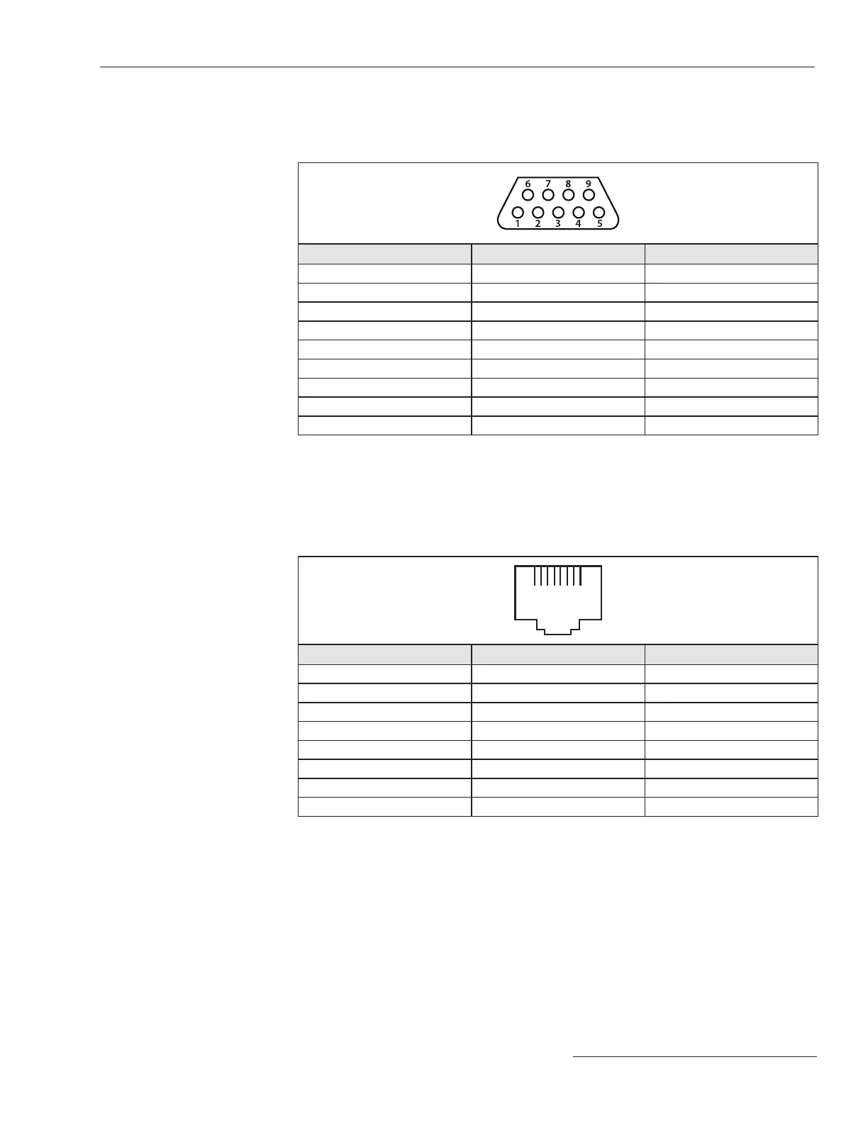
The RS-232 port of the gateway controller module (green box) is congured as data-
terminal equipment. See Table 4.
Table 4. Gateway Controller Module RS-232 Interface Pinout
Pin Function Description
1 NC No Connection
2 RX from Radio RS-232 Receive
3 TX to Radio RS-232 Transmit
4 NC No Connection
5 TX to Radio GND Signal Ground
6 NC No Connection
7 RTS to Radio Request to Send
8 CTS to Radio Clear to Send
9 NC No Connection
Ethernet Ports 1 and 2 use RJ-45 connectors with the pinout shown in Table 5. They
are auto-sensing for assignment of transmit and receive lines (no crossover cables
required) and auto-negotiate for 10-Mbps or 100-Mbps data rates, as required by the
connected device.
Table 5. Ethernet Ports Pinout
1 8
Pin Function Description
1 TXD+ Transmit
2 TXD- Transmit
3 RXD+ Receive
4 NC No Connection
5 NC No Connection
6 RXD- Receive
7 NC No Connection
8 NC No Connection
Interface Pinouts
Appendix A

 Loading...


