16 S&C Instruction Sheet 461-509
Installing Remote Antenna Kits
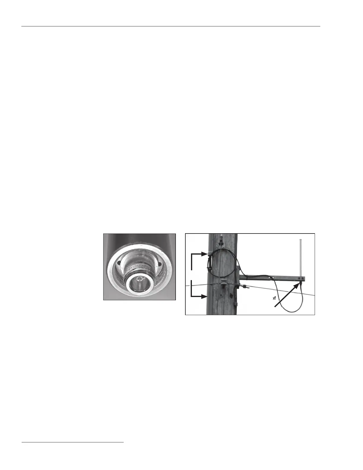
Figure 7. Do not block antenna
drain holes.
Antenna
Figure 8. The remote antenna.
The 403- to 470-MHz, 2-dBi antenna kit includes an omnidirectional antenna with an
N-male connector, pole mounting and bracket BM-1009, 2-shrink tubing, grounding kits
for the LMR-400, and a weather-resistant cable tie. 40-foot (12.2-m) or 60-foot (18.3-m)
coaxial cable length options are available.
Follow these steps to install Remote Antenna Kit 903-002702-02/01:
STEP 1. Install the antenna on the antenna bracket with one U-bolt. The white antenna
mast should be above the bracket, with only the brass base clamped in the
bracket.
STEP 2. Attach the antenna bracket to the pole. The pole should not block the line of
sight to other antennas.
STEP 3. Slip the supplied cold-shrink tube over the antenna cable and connect the end
where the shrink tube was applied to the antenna. Tighten nger-tight.
STEP 4. Wrap the cable connector inside the antenna with one piece of vinyl mastic
tape. Don’t stretch excessively, and do not block the antenna drain holes. See
Figure 7.
STEP 5. Apply the second piece of tape overlapping the end of the rst piece and tightly
cover the cable end of the connector.
STEP 6. Align the end of the cold-shrink tube ush with the bottom of the antenna and
shrink it over the tape and cable.
STEP 7. Tie-wrap the cable to the antenna bracket. Loop and secure any excess antenna
cable near the pole. Use of a U-guard is recommended to protect the cables. Do
not use staples. See Figure 8.
STEP 8. Slip a cold-shrink tube over the control end of the antenna cable and connect
the cable to the surge suppressor at the bottom of communications gateway
box. Waterproof this connector to industry standards.
Installing Remote
Antenna Kit
903-002702-02/01
U-guard
Waterproof
antenna
connector

 Loading...


