12 S&C Instruction Sheet 461-509
Installing and Replacing a Radio
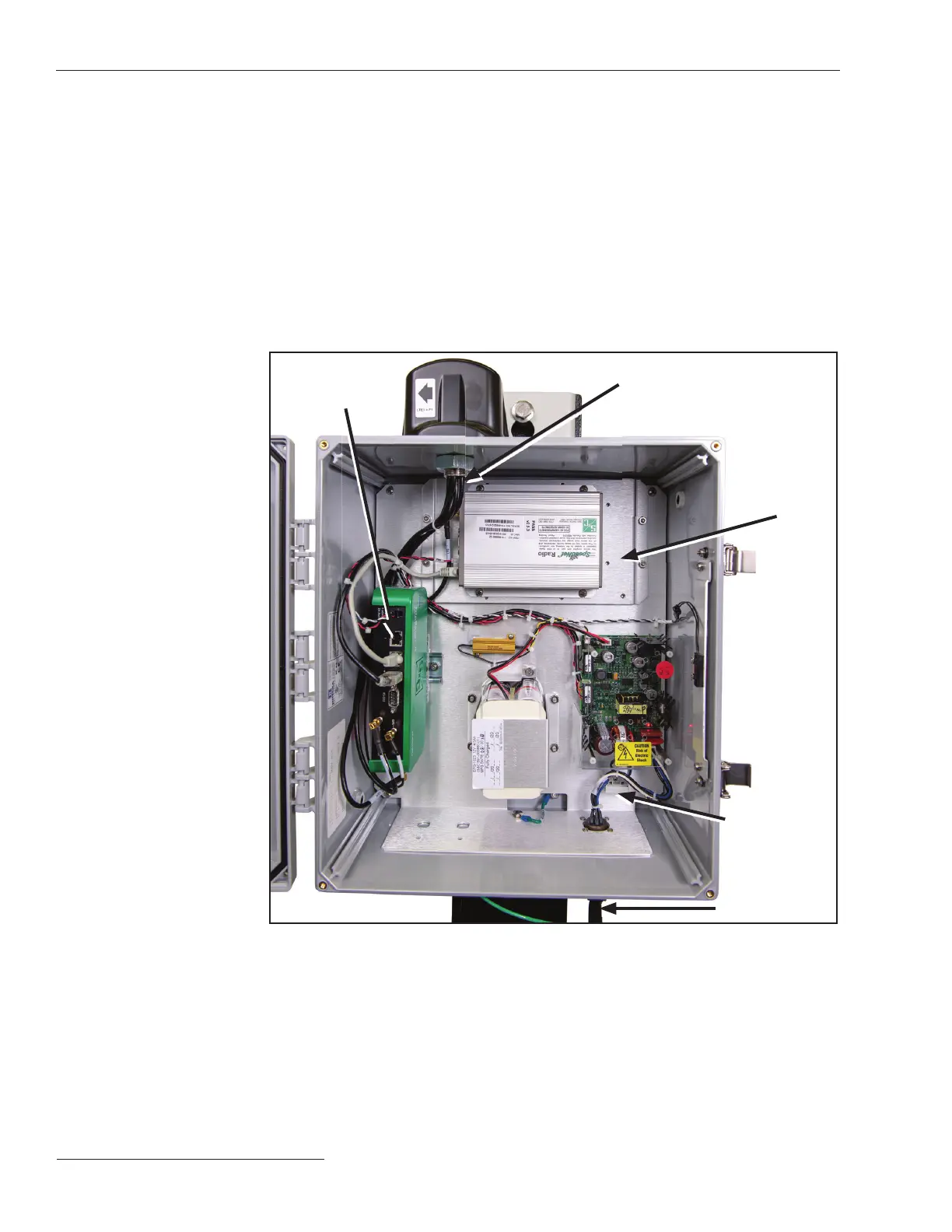
A radio providing eld-area network capability for SCADA applications, if speci ed, is
furnished factory-installed in the communications gateway. Alternately, the customer
may install a user-furnished radio. See Figure 4.
Follow these steps to install a radio in the communications gateway:
STEP 1. Disconnect the ac power cable connected to the bottom of the gateway and then
disconnect the ac line fuse located at the lower right corner of the gateway box.
STEP 2. Install the radio on the mounting plate using user-furnished hardware.
STEP 3. The wiring harness on most radios includes a power plug and data-port
connectors (Ethernet or RS-232 serial). Insert the power plug in its receptacle.
As applicable, connect the Ethernet connector to Port 2 of the green gateway
controller or insert the serial connector in its receptacle on the gateway
controller.
Radio
mounting
plate
Ethernet
Port 1
Ac line fuse
Antenna connector
Ac power cable
Figure 4. Installing a radio.
Installing a New Radio

 Loading...


