2 Introduction
2.4 Back Panel
Page 16
BP-200 plus
Art. no.: 2.510701 rev.: c
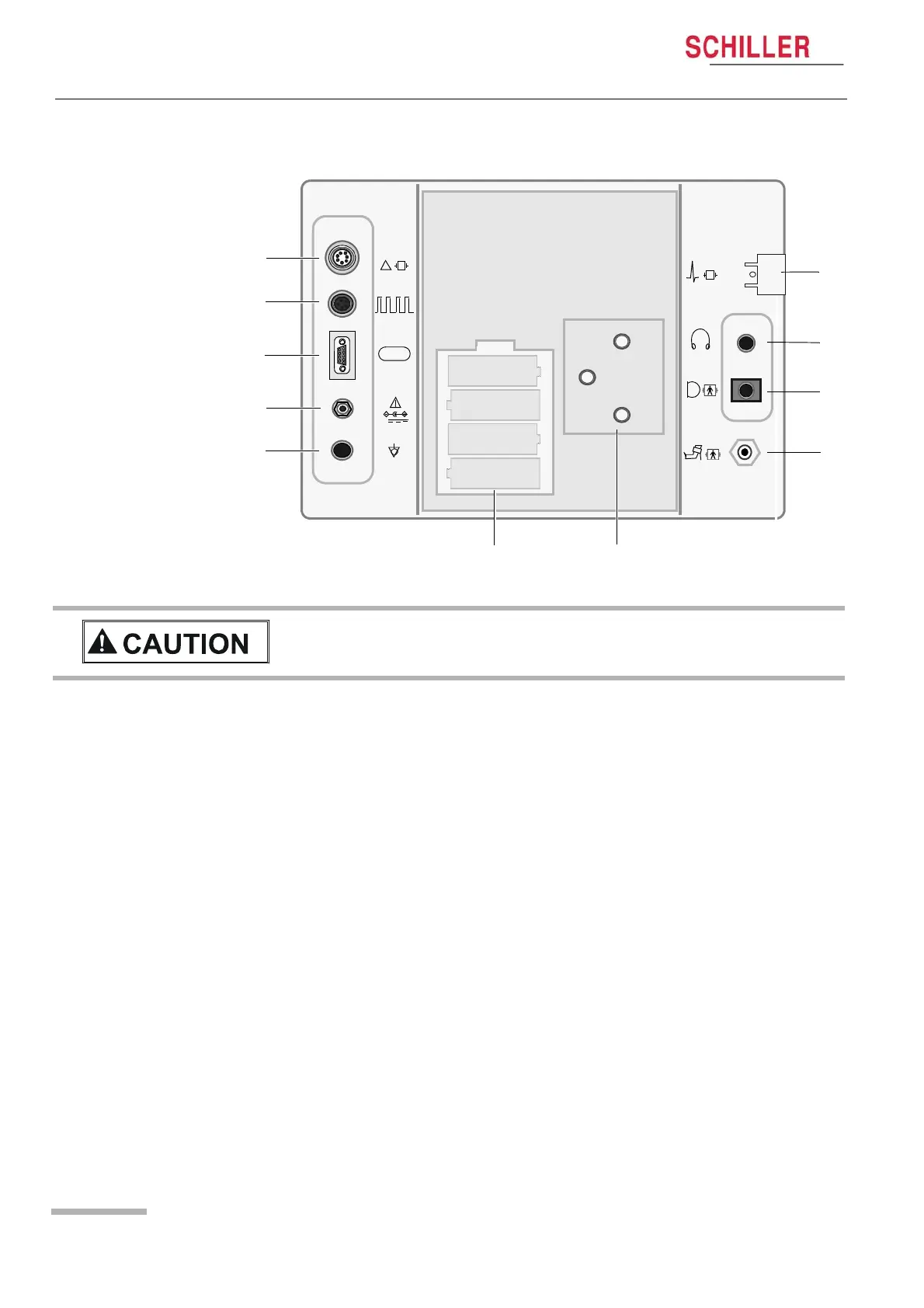
2.4 Back Panel
Patient Connectors / Sensors
(1) SpO
2
(Option) (see page 40).
(2) ECG trigger (from host system).
(3) RS-232 (for communication with host system).
(4) 9 V dc power input.
(5) Potential equalisation.
(6) Back-up battery compartment (four AA batteries).
(7) Unit Mounting plate.
(8) Air cuff connector.
(9) Microphone cuff connector.
(10) Head phone output (see page 39).
(11) ECG Cable Connector (Option) - not used when connected to a host system.
SpO
♥
!
RS-
9V
1
2
3
4
5
6 7
♥
11
10
9
8
+
+
+
+
V All externally connected hardware must be approved by SCHILLER. Connection
of any hardware not approved by SCHILLER is at the owner‘s risk. The unit
guarantee may also be invalid. (also see page 8).