Page 31
Art. no.: 2.510701 rev.: c
Blood Pressure Measurement 4
User Guide Using the BP-200 plus in Standalone Mode 4.2
BP-200 plus
4.2 Using the BP-200 plus in Standalone Mode
4.2.1 Connecting the ECG Patient Cable
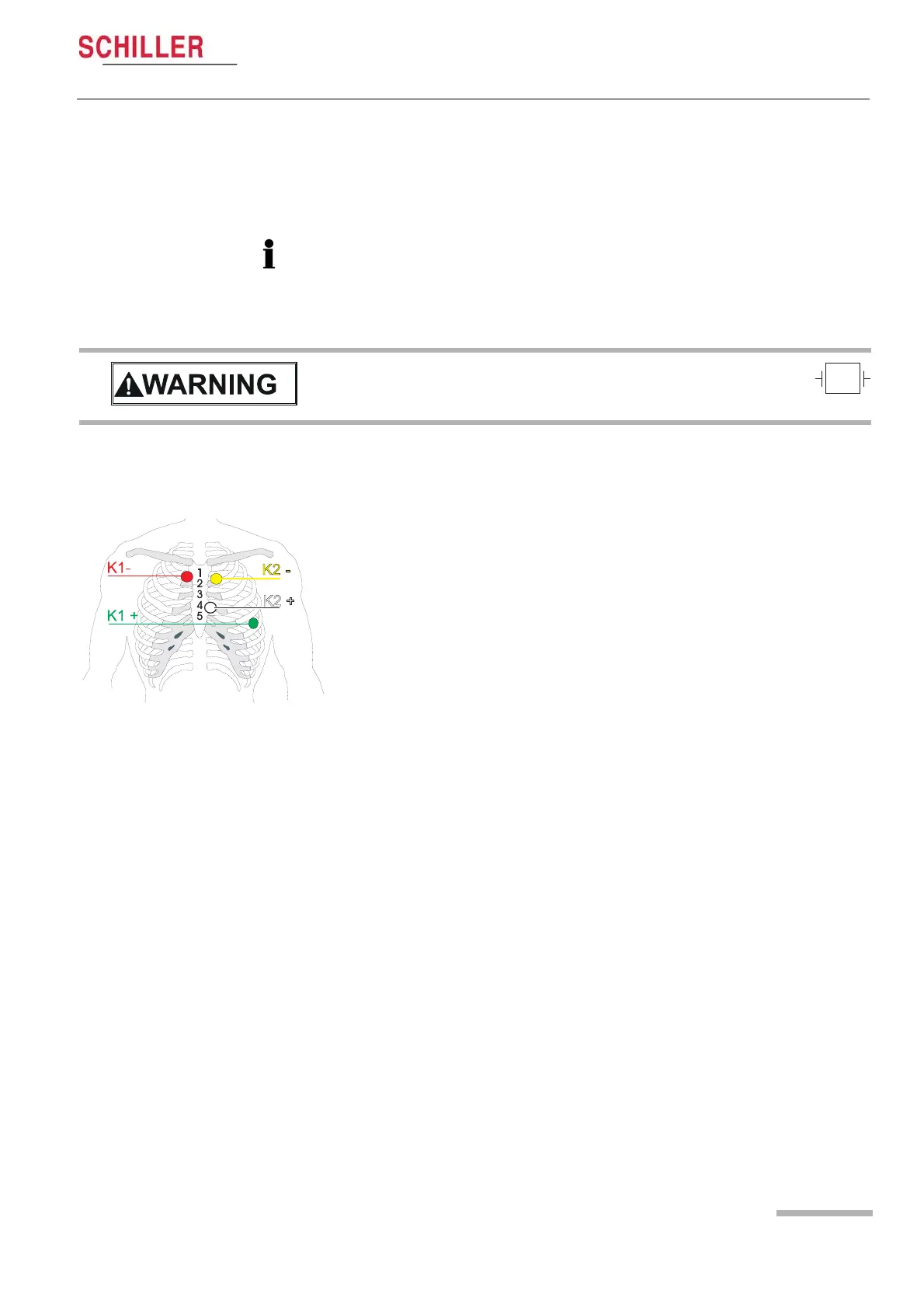
The BP-200 plus uses a 4-lead cable for 2-channel recording. The BP-200 plus uses
both channels to determine the QRS pulse. The recommend electrode positions to
obtain an good trigger are as follows:
4.2.2 SpO2 Measurement
If SpO2 measurement is to be taken apply sensor (see page 40).
Important
The guidelines for patient electrode placement are provided as an overview only.
They are not a substitute for medical expertise.
The colours shown here are according to code 1 (European) requirements.
V Danger of destroying the device during defibrillation. The device is CF
protected only when the original SCHILLER patient cable is used.
• Channel 1 positive (K1+) = green
• Channel 1 negative (K1-) = red
• Channel 2 positive (K2+) = white
• Channel 2 negative (K2-) = yellow
Form a stress loop in every cable and secure them with adhesive strips to relieve the
electrodes (strain relief).
A bipolar lead system (one positive and one negative lead) for each channel. Channel
1 approximates to modified lead V5 and channel 2 approximates to modified lead V2.