Assembly
14.00 | SRU-plus 20 - 60 | Assembly and Operating Manual | en | 389443 45
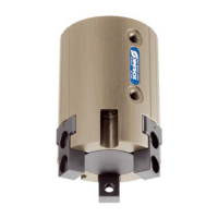
5.5.2 Mounting MMS 22 magnetic switch
CAUTION
Material damage due to an incorrect tightening torque!
If the threaded pin is tightened with an incorrect tightening
torque, the product may be damaged.
l
Observe a maximum tightening torque of 10 Ncm for the set-
screws.
The sensors can be mounted via four grooves in the housing of
the product.
We recommend the use of four magnetic switches to monitor the
center position:
l
Monitoring the end position A
l
Monitoring the end position B
l
Monitoring for the approach to the center position from end
position A
l
Monitoring for the approach to the center position from end
position B
1. Connect magnetic switch and secure cable, see sensor
assembly and operating manual.
2. Actuate air connection A (4).
ð Pinion (2) swivels towards the end position.
3. Slide the first magnetic switch (6) into a groove (5).
Or: Screw magnetic switch (6) into a groove (5) (1).
4. Slide magnetic switch (6) until it switches and the LED (7)
illuminates.
5. Tighten set screw (8).
ð Tightening torque: 10 Nm