IRD-2600 / IRD-2800
Integrated Receiver Decoders
P/N 2349-72784-00 Page 2-5
2.4.2. Front End Panels
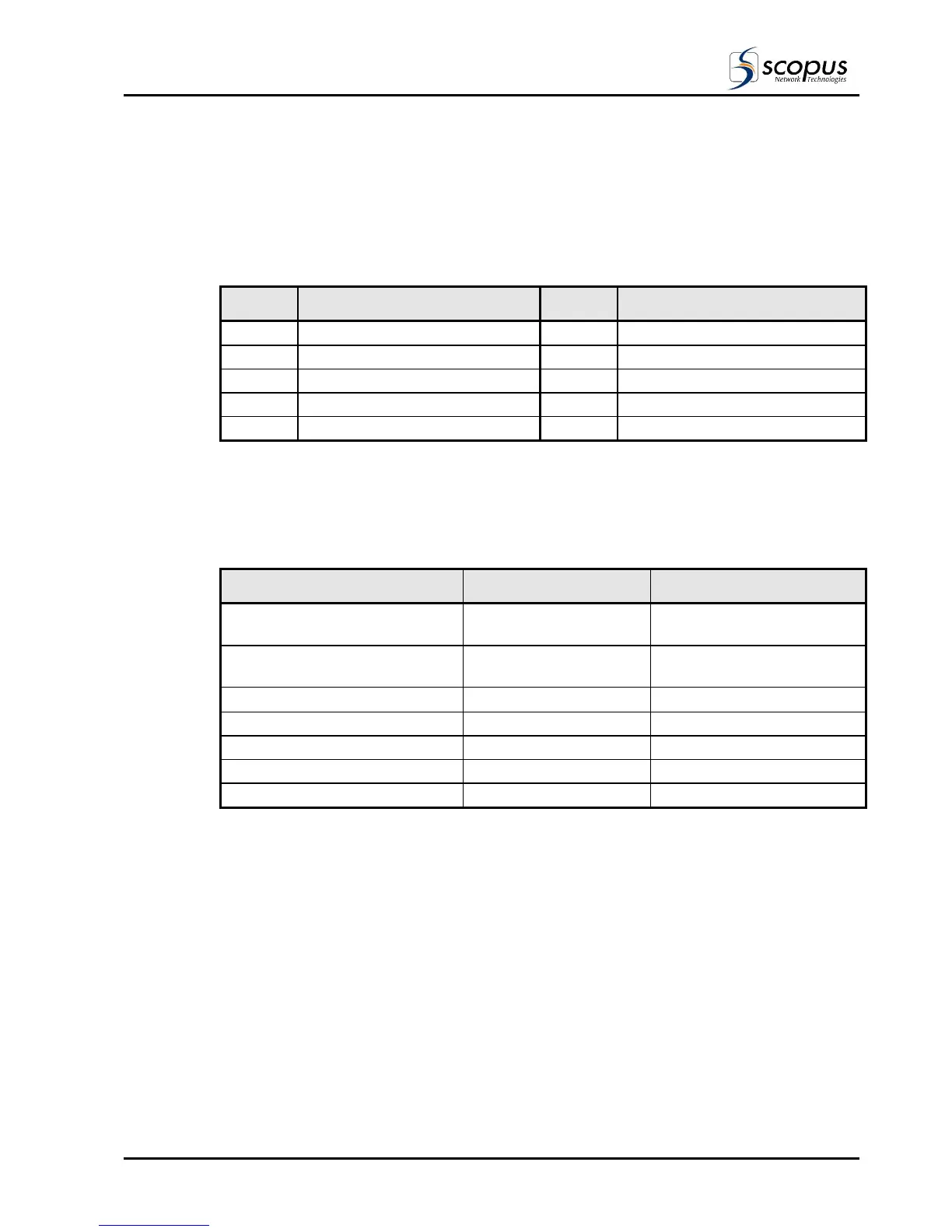
All front-end panels provide an RS-422/GPI connector for the input transport stream to the
IRD. Table 2-1 describes the functionality of the signals available on the connector.
Table 2-1: RS-422 Serial Input/GPI Pin Out Designations
PIN DESIGNATION PIN DESIGNATION
1
Clock Return (-)
6
GPI 1- NO (option)
2
Clock (+)
7
GPI 1-NC (option)
3
Data Return (-)
8
N/C
4
Data (+)
9
N/C
5
GPI 1-Common (option)
2.4.3. Decoder Cable Connections
The Decoder section of the IRD is comprised of Audio outputs, Video outputs, Data output,
and a Control connection (See Table 2-2 for the Decoder cables).
Table 2-2: Cables and Connectors for Decoder Section
INTERFACE CONNECTOR TYPE CABLE TYPE
Analog Audio Out left RCA (unbalanced)
XLR (balanced)
Shielded Audio Cable
Analog Audio Out right/mono RCA (unbalanced)
XLR (balanced)
Shielded Audio Cable
Video Out, S-Video Y/C
75 Ω DIN connector
Super Video Cable
Composite Video Out, CVBS1 BNC RG-59
Composite Video Out, CVBS2 BNC RG-59
Data Output (RS-232/RS-422) 9 PIN D-Type Serial Cable
Control (RS-232/RS-485) 9 PIN D-Type Serial Cable