User Manual
Chapter 2. Installation
Page 2-6 P/N 2349-72784-00
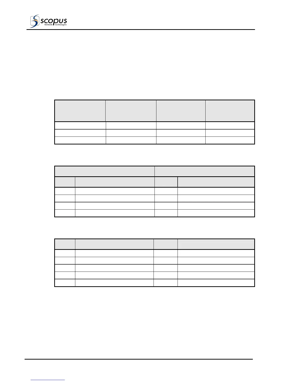
2.4.4. Terminal Control and Data Connections
The IRD supports terminal control from a standard PC via a Serial RS-232 or RS-485 cable.
Table 2-3 and Table 2-4 detail the pin-to-pin and signal assignment of the RS-232 and
RS-485 cables, respectively.
Table 2-5 details the pin designations for Data output (RS-422 and RS-232). These two data
flow protocols can be simultaneously enabled over the connector interface.
Table 2-3. RS-232 Control Cable Pin-to-Pin
9 PIN D-TYPE
CONNECTOR (PC)
25 PIN D-TYPE
CONNECTOR (PC)
9 PIN D-TYPE
CONNECTOR
(IRD)
SIGNAL
DESCRIPTION
2 3 3 PC-RxD
3 2 2 PC-TxD
5 7 5 GND
Table 2-4: RS-485 Control Cable Pin-to-Pin Designations
PC RS-485 9 PIN D-TYPE CONNECTOR IRD 9 PIN D-TYPE CONNECTOR
PIN DESIGNATIONS PIN DESIGNATION
1 RB 1 TX +
6 RA 6 TX -
8 TB 8 RX +
9 TA 9 RX -
Table 2-5: RS-422/RS-232 Data Output Pin Out Designations
PIN DESIGNATION PIN DESIGNATION
1 RS-422 Clock Return 6 RS-422 Clock
2 RS-232 RxD 7 RS-422 Data Return
3 RS-232 TxD 8 RS-422 Data
4 Manufacturer Test Point 9 Manufacturer Test Point
5 Ground